Climate Control Zoning System II instruction sheet l 7
System setup
Important! Connect only one actuator for each
channel. Channels 01 and 02 have double outputs
(a and b) for two actuators.
Caution! Ensure that each actuator is connected to the
correct channel so that the thermostats are controlling
the correct loops.
1. Attach the full assembly, or parts of it, to the wall either
with a DIN rail or by using wall screws and plugs. If installing
the controller inside a metal cabinet, locate the antenna
outside the cabinet.
2. Connect the antenna to the controller using the supplied
antenna cable.
3. Connect the actuators.
4. Insert batteries into the thermostats.
5. Connect optional external sensor (A3800167 only).
6. Set the desired DIP switch setting (A3800167 only).
7. Check that all wiring is complete and correct for the
actuators and output (to pump relay or boiler).
8. Close the 24 VAC compartment of the controller and
tighten the xing screw.
9. Connect the power cable to a 24 VAC transformer,
or if required by local regulations, to a junction box.
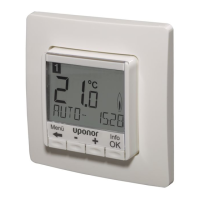
10. Set a time and date on the digital thermostats
(A3800167) and select thermostat control mode
in settings menu 04 (Default: RT).
Now, proceed to registering the thermostats to the correct base
unit (if multiple exist in the system). See pages 8-9 for details.
 Loading...