Do you have a question about the Uponor Heat-only Thermostat and is the answer not in the manual?
Install thermostat approx. 5 ft. (1.5m) above floor on smooth surface. Avoid specific locations like outside walls or near windows.
Mounts to wall or electrical box. Composed of back plate and controller. Follow steps for attachment and wiring.
Connect power wires to Rh/W terminals & optional floor sensor to SEN1/COM terminals.
Align tabs, hinge top, then press bottom until controller clicks into place.
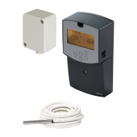
Install sensor and wire for easy replacement. Use conduit in lightweight apps. Use insulation for joist/Quik Trak.
Test sensor resistance before closing up. Use multimeter & thermometer to compare resistance to temperature values.
Controls hydronic radiant applications using differential and PWM for comfort & efficiency.
Maintains room air temperature based on desired setting when no floor sensor is connected.
Maintains room air temp and minimum floor temp. Air sensor takes over when outdoor temp drops.
Disables air sensor for applications like bathrooms. Maintains only the floor temperature.
Heating call begins when air temp drops 1°F (0.5°C) below setpoint and ends when it rises above.
Heating call begins when floor temp drops 1°F (0.5°C) below setpoint and ends when air temp rises 1°F (0.5°C) above.
Varies on-off cycles to manage heat when room temp is 1-3°F below setting, preventing overshoot.
Heats space to 37°F (3°C) if air temp drops below this when in OFF mode to prevent freezing.
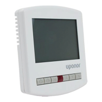
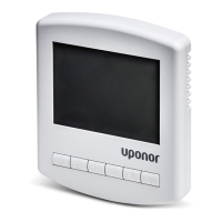
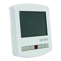
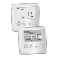
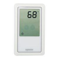
Explains icons and indicators on the touchscreen display for setpoint, mode, and status.
Change display units from Fahrenheit to Celsius by pressing AIR button twice and using arrow keys.
Limit room temperature based on energy use or needs. Press AIR button twice and use arrows.
Lower room set temperature for energy savings. Press AIR button three times and use arrows.
Limit floor temperature to protect flooring. Press FLOOR button twice and use arrows.
Operate heating by floor sensor only. Press AIR button, then lower set temp below lowest allowed setting.
Indicates floor sensor failure. Thermostat ignores slab setpoint and uses air temp of 65°F (18°C).
Air or floor sensor no longer detected. Check connections or replace sensor/thermostat.
Floor sensor connected but cannot read temp. Check wires, moisture, or sensor defect.
Displays 'LO' when air or floor temp falls below 33°F (0.5°C).
Displays 'HI' when air temp exceeds 95°F (35°C) or floor temp exceeds 140°F (60°C).
Specifies operating voltage (24 VAC) and maximum load (1.3 Amps).
Details shipping, storage, and operation temperature/humidity limits.
Provides a table correlating sensor temperature (°F/°C) with resistance (Ω).
Defines minimum and maximum range settings for air and floor temperatures.
| Brand | Uponor |
|---|---|
| Model | Heat-only Thermostat |
| Category | Thermostat |
| Language | English |