2 | uponorpro.com
Overview
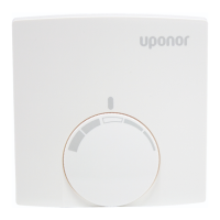
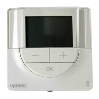
The Uponor Heat-only Thermostat (A3100101) is designed
for precise temperature control of hydronic radiant heating
applications. The thermostat includes an option to add a oor
sensor (A9010599) to measure oor temperature for enhanced
comfort and to protect the surface from overheating.
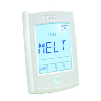
Additional features
• Operative temperature sensing
• Two-wire power sharing (easier installation)
• Capacitive touchscreen
• Color-enhanced display
• Slim, aesthetic design
Getting started
It is the installer’s responsibility to ensure this thermostat is
safely installed in accordance with all applicable codes and
standards. Uponor is not responsible for damages resulting
from improper installation and/or maintenance.
To avoid personal injury and damage to the
equipment:
• Read the manuals and documentation to familiarize yourself
with the product.
• Leave the manuals in an accessible location for the user’s
reference. (Note: Replacement manuals and documentation
on this product are available on uponorpro.com.)
• Turn off power to zone boards and other devices prior to
connecting the thermostat.
• Follow proper installation and operation practices for this
thermostat. Improper installation or use of the thermostat could
result in damage to the equipment.
• Do not open the thermostat. There are no serviceable parts
inside the thermostat and opening it will void the warranty.
This thermostat works effortlessly with other Uponor components.
However, some commonly used third-party devices (e.g.,
relays, zone valves, etc.) may have compatibility issues with
this thermostat. If connecting the thermostat to a third-party
control device, refer to that device’s installation instructions for
specic information regarding operation with a power-sharing
thermostat. A 10K Ohm, 0.25 Watt resistor is included in the
packaging when compatibility issues arise.
Refer to the wiring examples on page 7 for the most
common wiring applications. For additional information,
contact Uponor Technical Services at 800.321.4739 (U.S.)
or 888.994.7726 (Canada).
Tools required
• Small, athead screwdriver
• Phillips screwdriver (mounting hardware)
• Wire stripper and cutter
• Volt meter (oor sensor installations)
• Digital thermometer
• Multimeter
Installation overview
Prior to installing the Uponor thermostat, follow the instructions
below. (Note: Only experienced and trained professionals familiar
with low-voltage wiring should attempt to install the thermostat.)
1. Thoroughly read this manual to understand the proper
procedures for installation and operation. Failure to do so
could result in damage to the thermostat or its connected
equipment, creating a safety hazard.
2. Ensure the function and rating of the thermostat is suitable for
the application.
3. Uponor recommends installers use 18 AWG LVT wiring
for all low-voltage connections (as regulated by local
building codes).
Placing the thermostat
Where you place the thermostat is extremely important. Install
the thermostat approximately 5 ft. (1.5m) above the oor on
a smooth, at surface. Avoid mounting the thermostat in the
following locations.
• On outside walls
• On interior walls susceptible to solar gains
• On interior walls where the wall is unconditioned
• On a return-air chase
• Near windows
• Near replaces
• Near stoves, lamps, televisions or other electronics and
appliances
• In the corner of a room
• In damp areas
• Behind doors
• In areas where the temperature inside the wall differs from the
room temperature
Installing the thermostat
The thermostat can mount to a wall surface or a standard
electrical wall box using suitable hardware. The thermostat is
composed of two parts: the back plate and the controller. Refer
to the steps below to complete the installation.
1. Remove the back plate from the thermostat by pulling the
bottom of the plate away from the controller. The back plate is
hinged at the top of the controller.
2. Locate the back plate on the wall so the connection wires
are run through the rectangular wiring opening. The wiring
opening is right next to the wiring terminals.
3. Align the holes of the back plate with the holes in the electrical
wall box. Attach the plate with screws. If mounting directly on
sheetrock, use wall anchors and screws.
 Loading...