5. If the controller is mounted to a 2x4 electrical box, order a Cover Plate
for the 500 Series Controllers (part number A3040007). This plate
mounts to the electrical box and the controller mounts to the plate.
Ensure that the electrical box does not provide cold air to the controller.
Note: If the SetPoint 501s is used for remote sensing (i.e., the built-in
air sensor is disabled and an indoor sensor is used), mount the
controller in the desired location.
Rough-in Wiring
Note: 18 AWG or similar wire is recommended for all 24VAC wiring.
1. Strip all wires to
1
⁄4" (6mm) to ensure proper connection to the control.
2. Run wires from the 24VAC power to the controller. Use a clean power
source to ensure proper operation.
3. If using an optional sensor, install the sensor according to the appropriate
instruction sheet and run two wires from the sensor to the controller.
4. Run wires from the heating device to the controller.
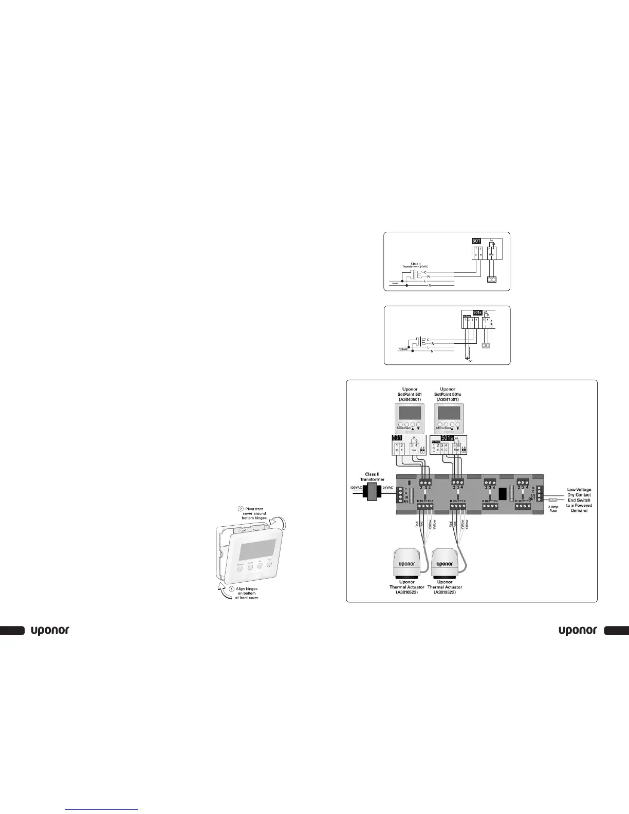
Wiring the Controller
Refer to the wiring examples on page 5 to properly wire the controller.
1. Connect the 24VAC power to the R and C terminals on the controller.
This connection provides power to the microprocessor and display of
the controller.
2. When wiring an optional sensor to the SetPoint 501s, connect the two
wires from the sensor to the Com and S1 terminals.
Note: The Heat terminals are isolated outputs. There is no power available
on these terminals from the controller. Use these terminals as a
switch for a 24VAC circuit. This circuit can operate a low-current,
24VAC device directly or an external relay to enable a line-voltage
or high-current device.
Installing the Front Cover
1. Align the hinges on the bottom of the front
cover with the bottom of the controller
mounting base.
2. Pivot the front cover around the bottom
hinges and push the top against the
mounting base until it snaps firmly in place.
(See Figure 3.)
Wiring Examples for the SetPoint 501 and SetPoint 501s
Refer to the figures below to wire 24VAC power and the optional sensor.
5
4
Section 2 — Installation
Figure 3:
Installing the Front Cover