Quick Guide
8. Insert batteries into the thermostats.
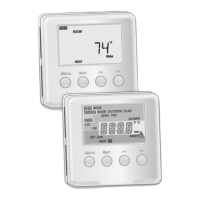
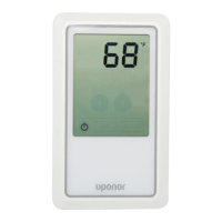
9. Select thermostat control mode (settings menu 04,
in digital thermostats only). Default: RT (standard
room thermostat).
10. Connect the power cable to a 230 V AC wall socket,
or if required by local regulations, to a junction box.
Register thermostats, the interface and other system
devices, in that order (next page).
Installation
1. Attach the full assembly, or parts of it, to the wall
either with a DIN rail or by using wall screws and
plugs.
If the controller is installed inside a metal cabinet,
then locate the antenna outside the cabinet.
2. Connect the antenna to the controller using the
supplied antenna cable (0.5 – 5m, CAT5e/CAT6).
3. Connect the actuators.
4. Check that all wiring is complete and correct:
• Actuators
• Heating/cooling switch
• Circulation pump
5. Ensure that the 230 V AC compartment of the
controller is closed and the fixing screw is tightened.
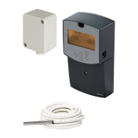
6. Connect optional external sensor (compatible
thermostats only).
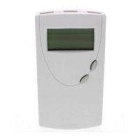
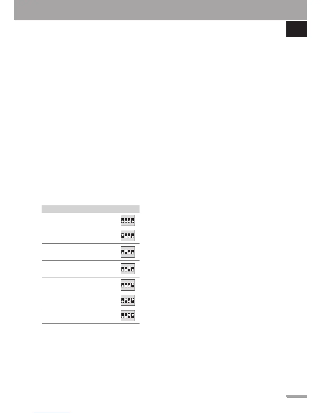
7. Set DIP switch on public thermostat T-163.
Function*
Switch
Standard room thermostat
 Loading...