Installation
Warning!
The transformer module is heavy and might
detach if the controller is held upside down
without the cover on.
NOTE!
Wires between transformer and controller card
needs to be disconnected prior to detaching.
NOTE!
Connect only one actuator for each channel.
Channels 01 and 02 have double outputs (a
and b) for two actuators.
Caution!
Ensure that each actuator is connected to the
correct channel so that the thermostats are
controlling the correct loops.
NOTE!
Registration of at least one thermostat must
be done before registering a system device.
Caution!
The switches in the public thermostat must
be set before the thermostat is registered.
Caution!
The switches, in the public thermostat, must
be set to one of the available functions,
otherwise it cannot be registered.
A. Attach the full assembly, or parts of it, to the wall
either with a DIN rail or by using wall screws and
plugs.
If the controller is installed inside a metal cabinet,
then locate the antenna outside the cabinet.
B. Connect the antenna to the controller using the
supplied antenna cable.
C. Connect the actuators.
D. Insert batteries into the thermostats and optional
timer.
E. Connect optional external sensor (compatible
thermostats only).
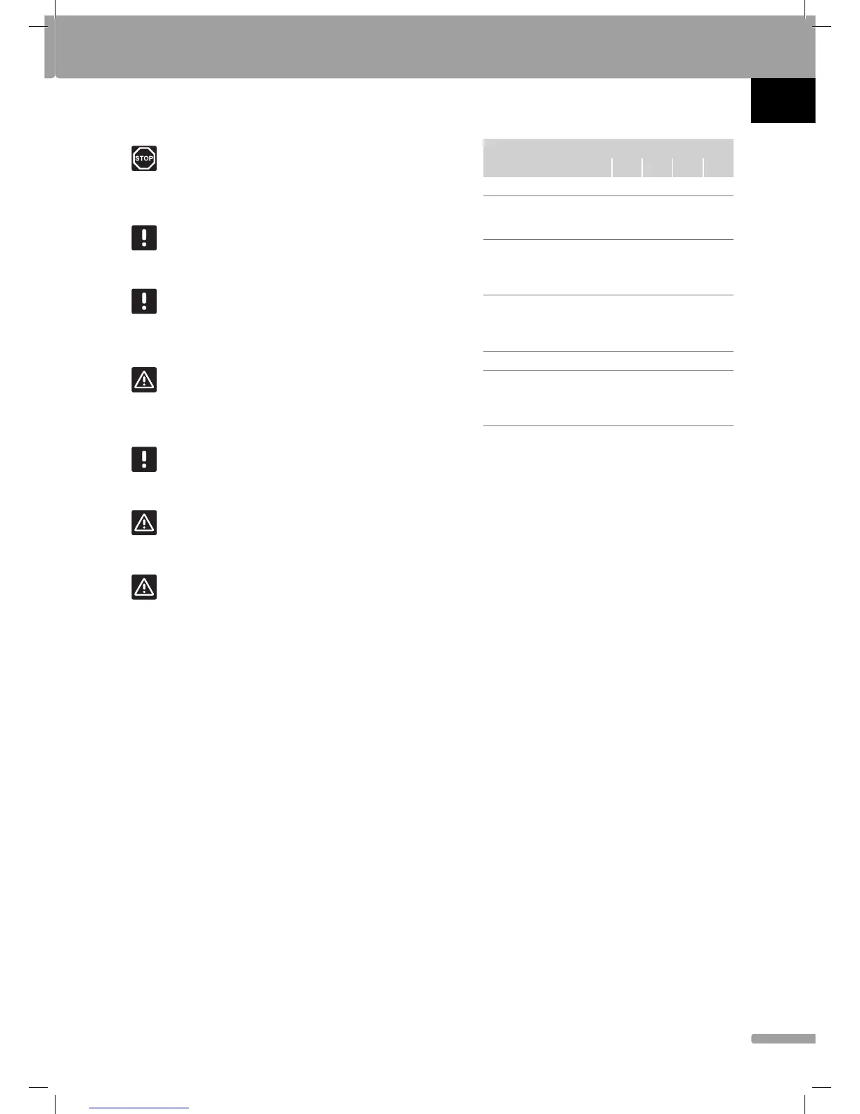
F. Set DIP switch on public thermostat T-163.
Function
Switch
1234
Standard room thermostat
Off Off Off Off
Standard room thermostat
together with a fl oor
temperature sensor
On
Off Off Off
Standard room thermostat,
or system device, together
with an outdoor temperature
sensor
Off
On
Off Off
System device where the
sensor input is used for
Comfort/ECO switch over
function
Off Off Off
On
Remote sensor
Off
On
Off
On
System device where the
sensor input is used for
heating/cooling switch-over
function
Off Off
On On
G. Check that all wiring is complete and correct:
• Actuators
• Heating/cooling switch
• Circulation pump
H. Ensure that the 230 V AC compartment of the
controller is closed and the fi xing screw is tightened.
I. Connect the power cable to a 230 V AC wall socket,
or if required by local regulations, to a junction box.
J. Set time and date on thermostats and timer (digital
thermostat T-168 and timer only).
K. Select thermostat control mode (settings menu 04,
in digital thermostats only). Default: RT (standard
room thermostat).
L. Register thermostats, the timer and other system
devices, in that order (next page).
QUICK GUIDE
UK
CZ
DE
DK
EE
ES
FI
FR
HR
HU
IT
LT
LV
NL
NO
PL
PT
RO
RU
SE
SK
9
UPONOR SMATRIX WAVE · QUICK GUIDE
 Loading...