32
−−−−
sec.3m
2 VOICE - Technical Manual
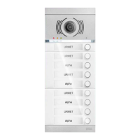
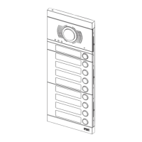
PUSH BUTTON PANEL
ALPHA PUSH BUTTON PANEL
PARAMETER CONFIGURATION WITHOUT WiFi CONNECTION
PARAMETER CONFIGURATION WITHOUT
WIFI CONNECTION
The conguration is performed directly on the device. The parameters
listed below can be congured and the value can be set by means of
LEDs (1) and (4).
PARAMETER 1: door unit type
This parameter is used to set the door audio and audio-video door
unit as primary or secondary. All the users in the system may be called
from the main door unit. A secondary door unit may only call the users
of the riser to which it belongs. Users who receive the call can identify
the source of the call by the tone.
PARAMETER 2: door unit ID
If main door unit type is set under previous parameter, this parameter
can be used to change the ID from 0 to 1 because various main calling
stations with different ID can be present in the system.
If, on the other hand, a “secondary” door unit type is set under
previous parameter (which by default is named riser 0), this parameter
can be used to change the ID from 0 to 1 because two secondary
calling stations with different ID can be present in the same riser.
PARAMETER 3: door opener
This is used to manage lock door opener mode; possible options are
“Free” or “Privacy”. In “Privacy” mode, the electric lock may only be
activated by pressing the door opening button on the calling station
when an audio conversation has been established or when after having
received a call or auto-on function either a video connection has been
established.
In “Free” mode, instead, the indoor station door opener button will only
open the door unit electrical lock only if the door unit is congured
as main or the user belongs to the same door unit riser. This riser is
dened by the secondary door unit ID setting. This function is typically
used for secondary stations.
The above applies to the vehicle and pedestrian gate electrical lock.
PARAMETER 4: call button enabling
This parameter can be changed to enable call buttons (2) and (7)
present on the front part of the door unit.
Specically, the buttons can be enabled on the call button only (7), on
both buttons or on no button.
PARAMETER 5: button enabling to call switchboard
If the door unit was congured as main unit (by means of parameter
1), then call buttons (2) and (7) can be enabled to call the switchboard.
If the buttons are enabled to call the switchboard
(parameter 5 enabled) if will not be possible to congure
the call button enabling function (parameter 4).
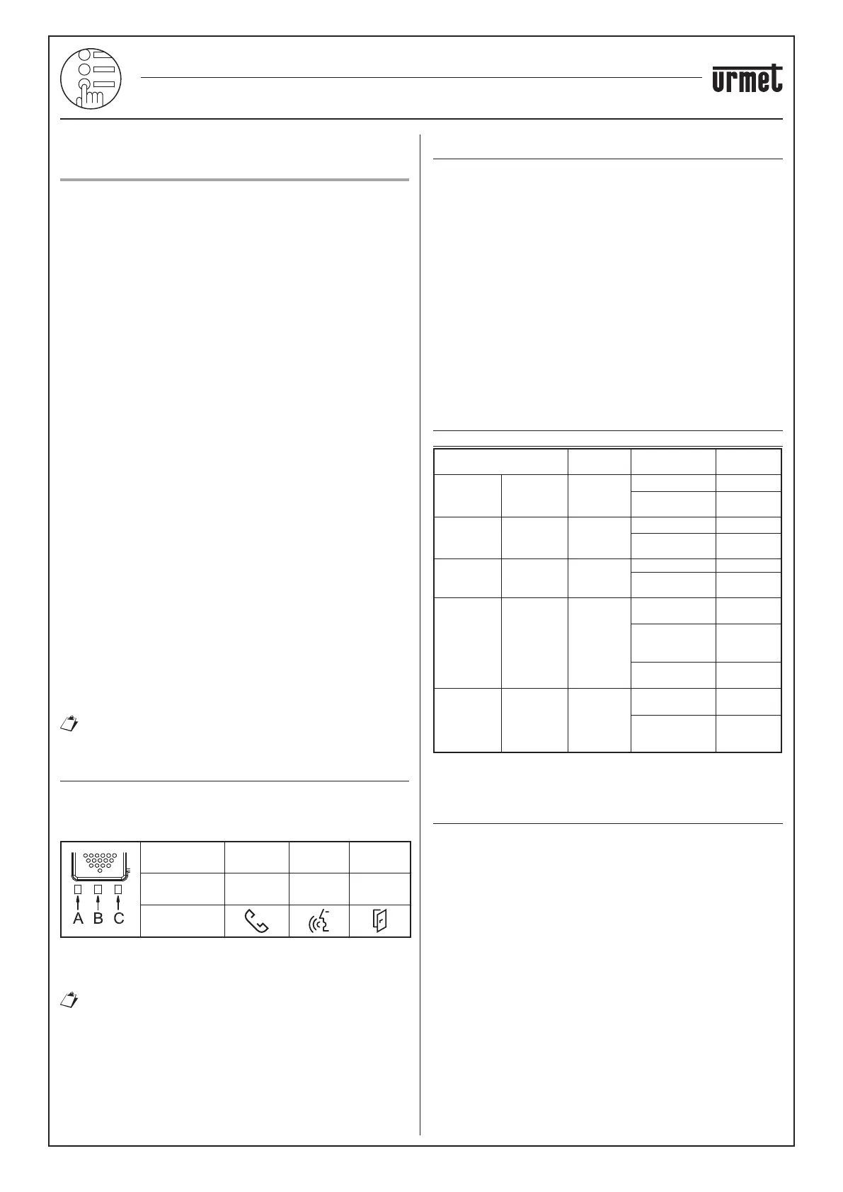
CONTROLS AND DISPLAYS FOR CONFIGURATION
The conguration and the respective set values are displayed by
means of:
• LED (1) for programming, as shown below:
LED
reference
A B C
LED colour
Red or
Green
Orange
Red or
Green
Symbol on
front
LED (4): LED for displaying the set parameter value;
BUTTON (7): button for changing and/or conrming the parameter;
PROGRAM button (11): button for starting the conguration.
See the “Structure” chapter for the location of these
components on the door unit.
READING/CONFIGURATION SEQUENCE
Each parameter is associated with a colour of the LEDs (1) for
programming and the set value is indicated by the LED (4) as follows:
• LED (4): OFF
• LED (4): ON STEADY
• LED (4): ON BLINKING
The steps for reading or conguring the device are shown below:
1. Press the PROGRAM button (11) briey (less than 2s): the LEDs (1)
will blink on the door unit [A: red, B: orange, C: red] to indicate that
the device is in programming mode;
2. Press the BUTTON (7) again briey to select the parameter to be
congured which can be identied by the LEDs associated with it
according to the table shown in the following chapter.
3. Select the parameter and hold the BUTTON (7) pressed for longer
(from 5 to 10 seconds) to set the parameter as indicated visually by
the LEDs (4).
4. Press the PROGRAM button (10) briey or wait for the timeout
after 10 minutes to end conguration mode.
PARAMETER ASSOCIATED TO PROGRAMMING
LED (1) COLOUR
Parameter to be
congured
LED (1) Parameter value
LED state
(4)
Parameter 1:
door unit
type
Led C:
Green
Main LEDs off
Secondary
LEDs on
steady
Parameter 2: door unit ID
Led C: Red
Address 0 LEDs off
Address 1
LEDs on
steady
Parameter 3:
door opener
Led B:
Orange
Privacy LEDs off
Free
LEDs on
steady
Parameter 4:
call button
enabling
Led A:
Green
No button
enabled
LEDs off
Only the calling
button (7)
is enabled
LEDs on
steady
Both buttons are
enabled
LEDs on
blinking
Parameter 5:
(*)
call button
association
with
switchboard
call
Led A: Red
Not active LEDs off
Active
LEDs on
steady
(*) Function only possible if door unit is congured as main unit.
POSSIBLE SYSTEM TYPES WITH CONFIGURATION
WITHOUT WIFI CONNECTION
Only some types of installations can be congured without WiFi
connection:
• Connection of one riser to a calling station.
• Connection of a riser with 4 backbones and up to 2 two calling
stations.
• Connection of 1 riser with 4 backbones to a main calling
station and one or two secondary calling stations.
• Connection of one riser with 2 main calling stations and 2
secondary calling stations.
All other types of installation can be congured via WiFi.
ALPHA PUSH BUTTON PANEL
 Loading...