EasyManua.ls Logo

urmet domus DUO 752 User Manual

urmet domus DUO 752
8 pages
To Next Page IconTo Next Page
Page #1 background imageLoading...
Page #1 background image
R
DS 752-012A LBT 8273
Mod.
752
CITOFONO VIVAVOCE PER SISTEMA DUO
HANDS FREE DOOR PHONE FOR DUO SYSTEM
INTERPHONE MAINS LIBRES POUR SYSTEME DUO
INTERFONO MANOS LIBRES PARA SISTEMA DUO
SPRECHANLAGE MIT FREISPRECHSYSTEM DUO
ΘΥΡΟΤΗΛΕΦΩΝΟ ΑΝΟΙΚΤΗΣ ΑΚΡΟΑΣΗΣ ΓΙΑ
ΤΟ ΣΥΣΤΗΜΑ DUO
Sch./Ref. 752/33
Pulsante apriporta
Lock release button
Touche d'ouverture de porte
Pulsador de apertura puerta
Türöffnertaste
Πλήκτρο κλειδαριάς
Tasto di attivazione fonia (mani libere)
Speech signal activation button (hands-free)
Touche activation phonie (mains libres)
Pulsador activación de conversación (manos libres)
Taste der Aktivierung der Gesprächfunktion (freihand)
Πλ
ή
κτ
ρ
ο ενε
ργ
οποί
η
σ
η
ς ο
μ
ιλίας
Led Blu fonia attiva
Speech signal active blue led
Diode bleue phonie active
Led azul conversación activa
Blaue LED Gesprächfunktion aktiv
Ενδεικτικό LED (μπλε) ενεργοποίη
σ
Led segnalazione porta aperta
Open door indicator led
Diode de porte ouverte
Led de indicación de puerta abiert
a
Led anzeige tür offen
Ενδεικτικό LED ανοικτής πόρτας
Tasto di servizio ausiliario
Auxiliary service key
Touche de service auxiliaire
Pulsador de servicio auxiliario
Taste für Senderdienste
Βοηθητικό πλήκτρο

Other manuals for urmet domus DUO 752

Question and Answer IconNeed help?

Do you have a question about the urmet domus DUO 752 and is the answer not in the manual?

urmet domus DUO 752 Specifications

General IconGeneral
Brandurmet domus
ModelDUO 752
CategoryIntercom System
LanguageEnglish

Summary

Urmet DUO System Door Phone Identification

Key Components and Controls

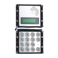
Identifies main buttons like door release and service keys, and indicator LEDs.

Multilingual Function Labels

Provides labels for buttons and LEDs in multiple languages for user understanding.

DUO System Installation and Setup

Mounting and Wiring Diagrams

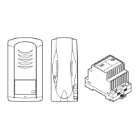
Visual instructions for physically installing the unit and connecting its wiring.

Important Trimmer Setting Warning

Crucial advice against altering factory default trimmer settings to prevent issues.

Supplementary Components

Electronic Buzzer Installation Guide

Instructions for installing the supplementary electronic buzzer for additional call functions.

Wiring Specifications and Best Practices

Minimum Conductor Cross-Section

Specifies the minimum required wire gauge for various circuits based on distance.

Twisted Pair Wiring Recommendation

Mandates the use of twisted pair wiring for improved signal integrity and noise reduction.

System Configuration and Compatibility

Sinthesi Panel Module Arrangement

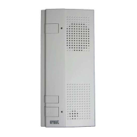
Guidance for arranging modules within Sinthesi panel frames as per product instructions.

Power Supply Unit Capacity

Details the maximum number of devices (22) a specific power supply unit can support.

System Wiring Diagrams and Connections

Multi-Utopia to Sinthesi Unit Connection

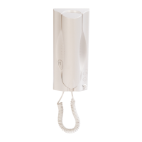
Illustrates the connection schematic for linking several Utopia door phones to a single Sinthesi door unit.

Technical Diagram Legend

Explanation of Diagram Symbols

Defines the meaning of all symbols used across the technical diagrams for clarity.

Model Interconnectivity and Volume Settings

Hands-Free Door Phone Model Interchangeability

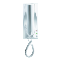
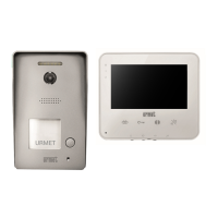
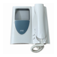
Information on which hands-free door phone models can be interchanged and their wiring.

Volume Adjustment Controls

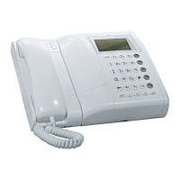
Describes the MAX, MIN, and MUTE settings for adjusting the calling volume.

Related product manuals