Lowes.com
SAFETY INFORMATION
IMPORTANT SAFETY INSTRUCTIONS
1. Turn power OFF before installing or servicing.
3. Do NOT remove the protective LED lens.
4. Do NOT look directly at lighted LEDs for any length of time.
5. Do NOT leave bare wires exposed outside the wall canopy enclosure.
6. Electrical requirements: 120 V AC, 60 Hz., 0.31A. Minimum 90° supply conductors.
7. Suitable for wall or eave mounting onto recessed or round surface mounted electrical boxes rated for
wet locations. Not suitable for ground mount electrical boxes.
8. Do NOT allow the sensor head to touch the LED head housing. Maintain at least 1 in. spacing
between the LED heads and the sensor head.
9. For proper operation and protection against water damage, the motion sensor adjustment controls
MUST be facing downward.
10. Do NOT mount below 5 ft.
11. Do not mount near other light sources that can compromise the dusk to dawn sensor.
12. This device complies with Part 15 of the FCC rules. Operation is subject to the following two
conditions: (1) This device may not cause harmful interference, and (2) this device must accept any
interference received, including interference that may cause undesired operation.
Before beginning installation of product, make sure all parts are present. Compare parts with package
contents list and hardware contents list. If any part is missing or damaged, do not attempt to install the
product.
Estimated Assembly Time: 45 minutes.
Tools Required for Assembly (not included): Phillips screwdriver and silicone adhesive caulking.
pools or bodies of water, or trees/bushes that move in the wind. All of these may trigger the motion
sensor security light and may be disruptive to the intended operation of the light. Do NOT install near
other sources of light. The other light sources can fool the dusk to dawn sensor into thinking it is daylight.
PREPARATION
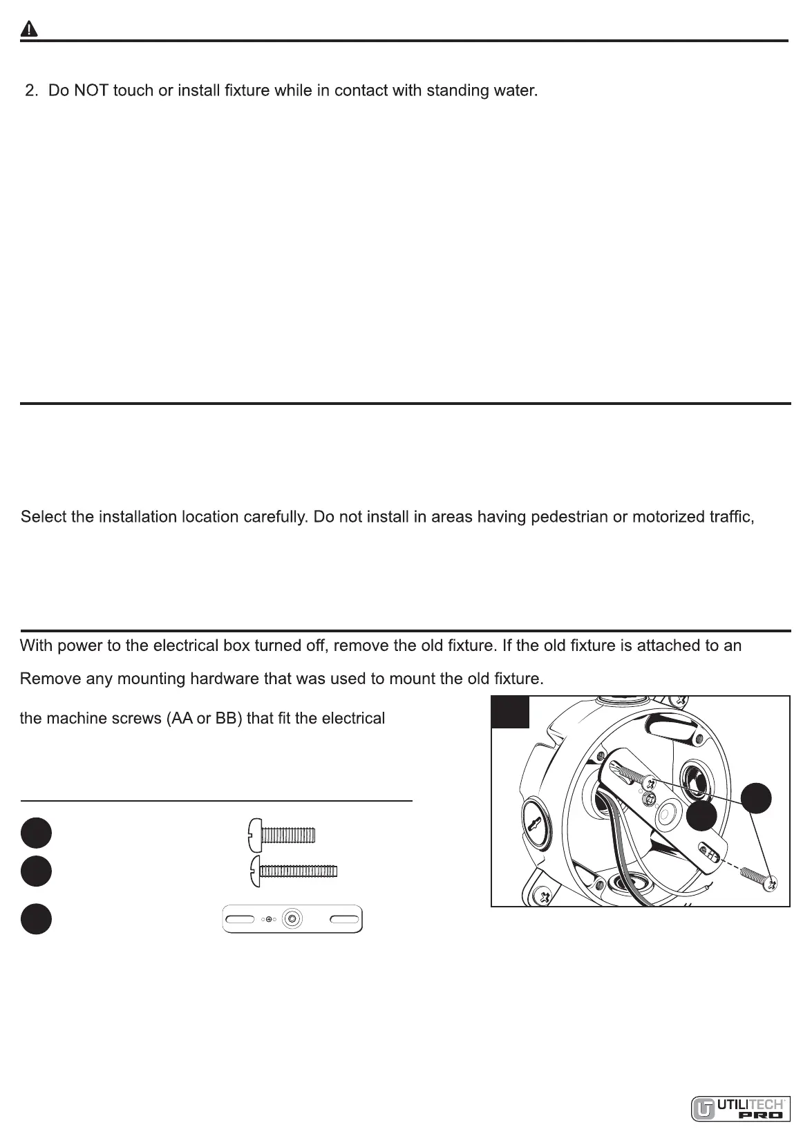
electrical box that has more than two wire leads, mark the wires to keep track of the correct ones to use.
1. Pull the supply wires out of the electrical box. Using
box, secure the mounting strap (CC) to the electrical
box, making sure that the side marked “FRONT” is
facing out.
3
INSTALLATION INSTRUCTIONS FOR ROUND SURFACE MOUNT ELECTRICAL BOXES
1
G
N
D
FRONT
CC
AA
Hardware Used
Machine Screws
x 2
AA
BB
Mounting Strap
x 1
CC
GND
FRONT
 Loading...