17
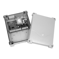
ATTENTION: it is necessary to turn off the
control unit power before doing the operations
mentioned here below. Please pay attention to the
way you connect the removable modules.
PLUGGING THE RECEIVER MODULE IN
WARNING LIGHT DESCRIPTION
The warning light shows in real time the state of the
gate:
STOP light off
IN PAUSE light always on
DURING OPENING the light flashes slowly (2 Hz)
DURING CLOSING the light flashes rapidly (4 Hz)
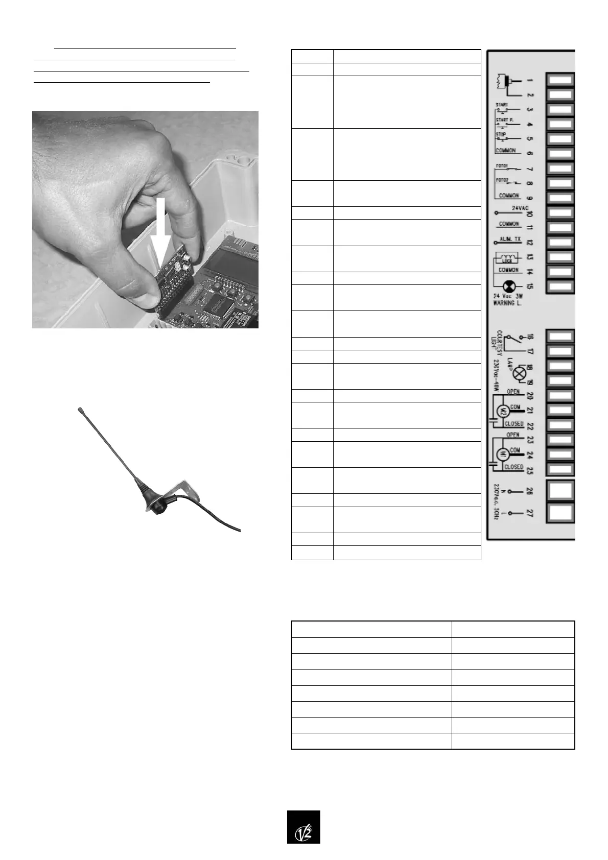
TERMINAL CONNECTION
TECHNICAL SPECIFICATIONS
Power supply 230 VAC 50 / 60 Hz
Max motors load 700 W
Max accessories load powered 24V 10 W
Working temperature -20°C ÷ +60°C
Protection fuse F1 = 5 A for line 230 VAC
Dimensions 295 x 230 x 100 mm
Weight 1600 g
IP protection 55
1.
2.
3.
4.
5.
6.
7.
8.
9.
10.–11.
11.–12.
13.–14.
14.–15.
16.–17.
18.–19.
20.
21.
22.
23.
24.
25.
26.
27.
Antenna
Antenna shield.
Opening control for the connection
of: control devices with normally
open contact, TTNC, VRD
Opening controls for pedestrian
access for the connection of:
control devices with normally open
contact, TTNC, VRD
Stop command
Contact normally closed
Common (-)
Photoelectric cell 1
Contact normally closed
Photoelectric cell 2
Contact normally closed
Common (-)
Power output 24 VAC for
photocells and other accessories
Photocell TX power supply for
functional tests
Electric lock or bolt 12 VAC
Warning light 24 VAC 3W
Contact for area lighting
230 VAC 10 A
Flashing light 230 VAC 40 W
Power output 230 VAC for motor
2 in opening phase
Common motor 2
Power output 230V for motor 2 in
closing phase
Power output 230 VAC for motor 1
in opening phase
Common motor 1
Power output 230 VAC for motor 1
in closing phase
Neutral 230 VAC
Power phase 230 VAC
WARNING: we suggest to use the external aerial
(model: ANS433) in order to guarantee the maximal
range.
 Loading...