ENGLISH
38
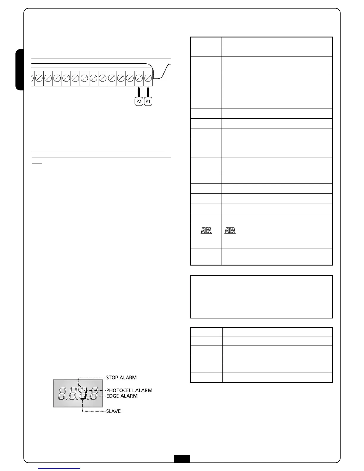
P1 Antenna
P2 Antenna shield
P3
Opening control for the connection of control
devices with N.O. contact
P4
Opening controls for pedestrian access for the
connection of control devices with N.O. contact
P5 Stop command. N.C. contact
P6 Common (-)
P7 Photocells type 1. N.C. contact
P8 Photocells type 2. N.C. contact
P9 Safety ribbons type 1 (fixed). N.C. contact
P10 Safety ribbons type 2 (mobile). N.C. contact
P11 Common (-)
P12 - P13
Power output 24 VAC for photocells and other
accessories
P13 - P14 Photocell TX power supply for functional test
B1 - B2 Courtesy light
B3 - B4 Flashing light 230VAC-40W
L Power phase 230 VAC
N Neutral 230 VAC
Interface
MAINS It shows that the control unit is power supplied
OVERLOAD
It shows that there is an overload on accessories
power supply
FC Limit switch
SW Release switch
ENCODER Encoder (accessory code 162328)
M Motor
C1 Running capacitor (BLACK SHEATH)
C2 Start off capacitor (RED SHEATH)
Here the description of the connectors already connected on
the left side of the control unit
m WARNING: Do not remove or invert the connectors
ELECTRIC CONNECTIONS TABLE
EXTERNAL AERIAL
We suggest to use the external aerial (model: ANSGP433) in
order to guarantee the maximal range.
Connect the antenna hot pole to terminal P1 of the control unit
and the braiding to terminal P2.
ADI INTERFACE
The ADI (Additional Devices Interface) interface of the control
unit allows the connection to V2 optional modules.
Refer to V2 catalogue or to the technical sheets to see which
optional modules with ADI interface are available for this control
unit.
m WARNING: Please read the instructions of each single
module to install the optional modules.
For some devices, it is possible to configure the mode for
interfacing with the control unit; in addition, it is necessary to
enable the interface so that the control unit can process the
signals arriving from the ADI device.
Please refer to the i.ADi programming menu to enable the ADI
interface and access the device configuration menu.
ADI devices use the display of the control unit to issue alarms or
display the configuration of the control unit.
NOTE:
If the ADI interface is not enabled (no device
connected), the segments remain turned off.
The device connected to the Adi interface is able to signal to the
control unit three alarm signals, which are displayed on the
control unit display as follows:
•
PHOTOCELL ALARMS
-
the upper segment comes on
:
the gate stops moving, when the alarm stops opening
restarts.
•
EDGE ALARM
-
the lower segment comes on
:
inverts motion of the gate for 3 seconds.
•
STOP ALARM
-
both segments start flashing
:
the gate stops and cannot restart until the alarm stops.
• SLAVE - segment steadily lit: it is used by the optional module
SYNCRO to indicate that the control unit is configured as
SLAVE.
mPLEASE NOTE: to install the encoder, please follow the
instructions reported in the manual provided with the
encoder carefully.
 Loading...