EasyManua.ls Logo

V2 VEGA-C 230V User Manual

V2 VEGA-C 230V
148 pages
Go to English
To Next Page IconTo Next Page
Page #1 background imageLoading...
Page #1 background image
ATTUATORE ELETTROMECCANICO 230V / 120V PER PORTE
BASCULANTI. CENTRALE DIGITALE INCORPORATA
230V / 120V ELECTROMECHANICAL ACTUATOR FOR SLIDING
DOORS BUILT-IN DIGITAL CONTROL UNIT
MOTOREDUCTEUR ELECTROMECANIQUE 230V / 120V POUR
PORTES BASCULANTES. ARMOIRE DE COMMANDE DIGITALE
INTEGRE
MOTOR ELECTROMECANICO 230V / 120V PARA PUERTAS
BASCULANTES. CUADRO DIGITAL INCORPORADO
ELEKTROMECHANISCHES STELLGLIED 230V / 120V FÜR
SCHWENKTÜRE. DIGITALSTEUERUNG EINGEBAUT
ELEKTROMECHANISCHE ACTUATOR 230V / 120V VOOR
KANTELPOORTEN. INGEBOUWDE DIGITALE STUURCENTRALE
I
GB
F
E
D
NL
VEGA-C
I
L n. 235
E
DIZ. 05/09/2013
V2 S.p.A.
Corso Principi di Piemonte, 65/67
12035 RACCONIGI (CN) ITALY
tel. +39 01 72 81 24 11 - fax +39 01 72 84 050
info@v2home.com - www.v2home.com
Question and Answer IconNeed help?

Do you have a question about the V2 VEGA-C 230V and is the answer not in the manual?

V2 VEGA-C 230V Specifications

General IconGeneral
BrandV2
ModelVEGA-C 230V
CategoryGate Opener
LanguageEnglish

Summary

General Safety Information

European Regulations Compliance

Automation must comply with European safety and EMC standards.

Installer Qualifications and Responsibilities

Installation requires skilled personnel; installer is responsible for compliance and safety.

Preliminary Checks and Identification

Technical Specifications

Installation of the Motor

Mounting the Actuator and Telescopic Arm

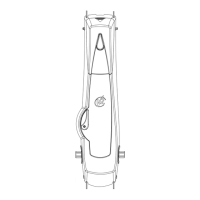
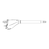
Details on fixing the anchoring bracket, telescopic arm, and drive tube.

Warning on Telescopic Arm Assembly

Crucial warning about ensuring free movement of the telescopic arm.

Adjustment of the Ends of Stroke

Opening End of Stroke

Procedure to adjust the left cam for the opening limit switch.

Closing End of Stroke

Procedure to adjust the right cam for the closing limit switch.

Control Unit Functions

Power Supply Connection

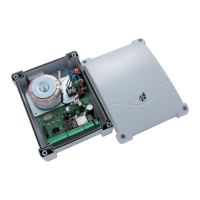
Electrical connection requirements for the control unit's power supply.

Control Unit Connections

Control Unit Wiring Summary

Electrical Connections Diagram

Detailed terminal list and diagram for all control unit connections.

Control Panel and Programming

Quick Configuration

Self-Learning Procedure

Guide to the automatic learning process for motor working times.

Control Unit Configuration

Parameter Configuration Table

Lists and describes all programmable parameters, default values, and descriptions.

Operation Defects and Troubleshooting

Common Error Codes

Explains common error codes and their causes/remedies for system faults.

Related product manuals