ENGLISH
35
8
.5 - SAFETY RIBBONS
The control unit PD11 is equipped with a specially provided
input to control safety ribbons; the intervention of the edge
r
everses the motion for 3 seconds either during the opening
and/or the closing phase. This input can control either the
classic edge with N.C. contact, or the conductive rubber ones
with nominal resistance 8,2 kohm.
Connect the cables of the safety ribbons between terminals J1
and J4 of the control unit.
m WARNING:
• When using more ribbons with N.C. contact, the inputs have
to be series connected.
• If using more conductive rubbers, the outputs have to be
cascade connected and only the last one has to be terminated
on the nominal resistance.
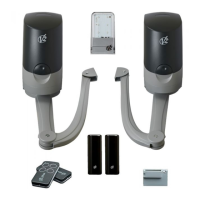
8.6 - STOP
For a better safety, you can fit a stop switch that will cause the
immediate door stop when activated. This switch must have a
normally close contact that will get open in case of operation.
In case the stop switch is operated while the door is open, the
automatic closing function will always be disabled.
To close the door again, you will need a start command (if the
start function in pause is disabled, it will be temporarily enabled
to allow the door release).
Connect the stop switch cables between terminal J3 and J4 of
the control unit.
The stop switch function can be activated by means of a
remote control stored on channel 3 (see relevant instructions
of MRx receiver).
8
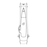
.7 - ACTIVATION INPUT
The PD11 central unit has an activation input
with N.A. contact that can be activated using
t
he pushbutton found on the motor lid or using
a transmitter (the pushbutton should be tuned
to channel 1 on the MRx receiver).
Use the J2 and J4 clamps to connect up an
external pushbutton.
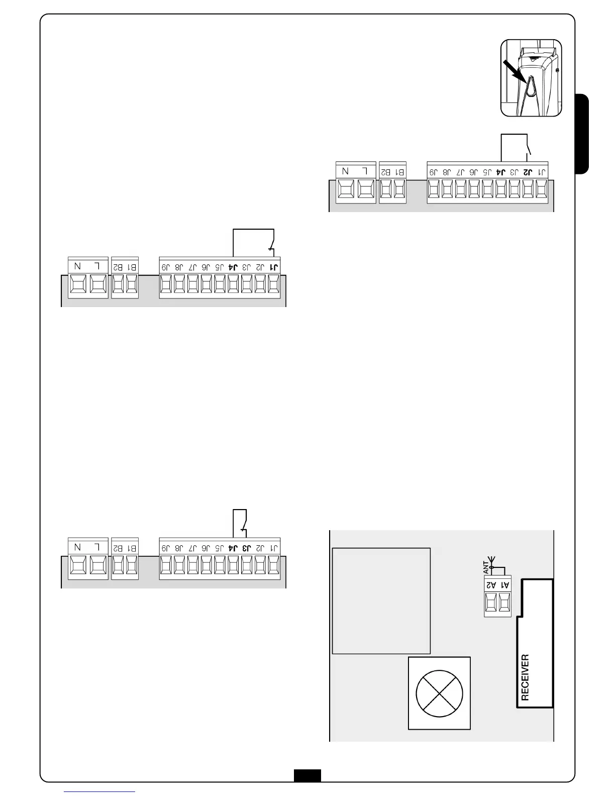
8.8 - PLUG IN RECEIVER
PD11 control unit is suitable for plugging in a Personal Pass MRx
receiver having a high-sensitivity super-heterodyne architecture.
m WARNING: it is necessary to turn off the control unit
power before doing the operations mentioned here below.
Pay attention to the way you connect the removable
modules.
MRx module receiver is provided with 4 channels and each of
them is suitable for a command of PD11 control unit:
• CHANNEL 1
쩚쩛
START
• CHANNEL 2
쩚쩛
NOT USED
• CHANNEL 3
쩚쩛
STOP
• CHANNEL 4
쩚쩛
COURTESY LIGHT
WARNING: Before programming 4 channels and function
logics read carefully the instructions of MRx.
8.9 - EXTERNAL AERIAL
We suggest to use the external aerial (model ANS433) in order to
guarantee the maximal range.
Connect the antenna hot pole to terminal A2 of the control unit
and the braiding to terminal A1.
 Loading...