Do you have a question about the V2 CITY2+L and is the answer not in the manual?
Connects the control unit to the main power line, respecting safety regulations.
Connects the motor(s) to the control unit, specifying terminals for opening and closing.
Configures various inputs like START, PEDESTRIAN START, STOP for gate control.
Connects a stop switch for immediate gate stopping, with safety considerations.
Connects photocells for safety detection during gate operation, with two types explained.
Connects safety ribbons (edges) to detect obstacles during gate movement.
Connects a 24V DC output for signal lights or flashing lights.
Connects a 230V output for courtesy or flashing lights.
Connects a 12V electric lock for securing the gate closure.
Connects limit switches and encoders for precise gate travel control and obstacle detection.
Connects an external aerial for improved radio range.
Connects an MR receiver module for remote control functionality.
Connects optional V2 modules via the ADI interface for expanded functionality.
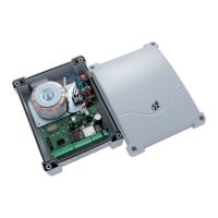
Detailed table and diagram of all electrical terminal connections for the control unit.
Explains how the unit signals when maintenance is needed based on cycle count.
| Motor Power Supply | 24V DC |
|---|---|
| Operating Temperature | -20°C to +55°C |
| Protection Class | IP44 |
| Protection Rating | IP44 |
| Power Supply | 230V AC |
| Motor Type | DC Motor |
| Safety Features | Obstacle detection |