ENGLISH
- 27 -
4 - DESCRIPTION OF THE CONTROL
UNIT
ThedigitalcontrolunitCITY2+isaninnovativeV2productthat
guaranteesasafeandreliableautomationofleafswingorsliding
gates.
CITY2+isprovidedwithadisplaythat,notonlymakes
programmingsimple,butalsoallowsacontinuousmonitoringof
the input statuses; in addition, thanks to a menu structure, the
workingscheduleandtheoperationlogiccanbeseteasily.
IncompliancewiththeEuropeanstandardsconcerningelectrical
safetyandelectromagneticcompatibility(EN60335-1,
EN 50081-1 and EN 50082-1) it has been equipped with the low
voltagecircuittotalelectricinsulation(motorsincluded)fromthe
networkvoltage.
Other characteristics:
• Powersupplyprotectedfromshortcircuitswithinthecontroller,
on the motors and on the connected accessories
• Adjustmentofthepowerbypartializingthecurrent
• Detectingobstaclesbymonitoringthecurrentonthemotors
(currentsensingprobe)
• Automaticlearningoftheoperationtime.
• Testsforsafetydevices(photocells,safetyribbonsandmosfet)
beforeeachopening.
• Deactivationofsafetyinputsthroughthecongurationmenu:
nojumperisrequiredforterminalsconcerningsafetydevices
thathavenotbeeninstalled,yet. Youwillonlyneedtodisable
thisfunctionfromitsrelevantmenu.
• Thedevicecanoperatewithoutmainspower,byusingthe
optionalbatterypack(code161212).
• Lowvoltageoutputthatcanbeusedforasignallightora
24Vashinglight.
• Auxiliaryrelaywithprogrammablelogicforcourtesylight,
ashinglightorotheruse.
• ENERGYSAVINGFUNCTION
5 - INSTALLATION
Installationofcontrolunitandsafetydevicesmustbecarriedout
with power disconnected.
5.1 - POWER SUPPLY
Models CITY2+ / CITY2+L
Thecontrolunitmustbefedbya230V50Hz(120V-50/60Hz
forthe120Vmodels)electricline,protectedbyadifferential
magnetothermalswitchcomplyingwiththelawprovisionsin
force.
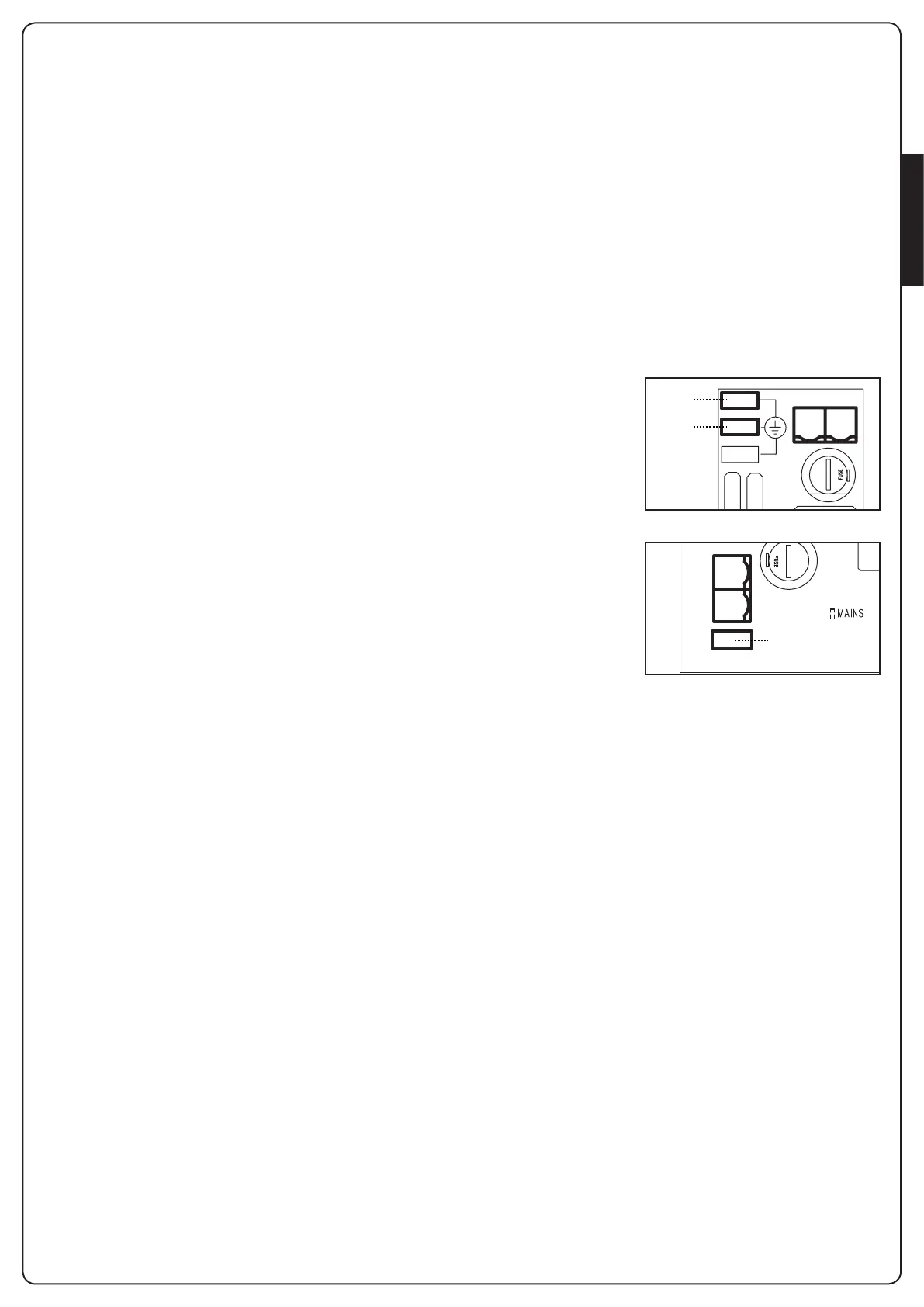
Connect phase and neutral to terminals L and Noftheboard
locatednexttothetransformer.
CITY2+
Connect the earth cable
ofthesystemtothepreset
fastonA
Connect the earth cable
ofthemotortothepreset
fastonB
CITY2+L
Connectthegroundcable
ofthesystemandof
motorstofastonA
Model CITY2+BC
Connect the +poleoftheECOLOGICbatteryboxtotheBAT+
terminalonthecontrolunit(useafastonfortheconnection)
Connect the -poleoftheECOLOGICbatteryboxtotheBAT-
terminalonthecontrolunit(useafastonfortheconnection)
5.2 - MOTORS
CITY2+ control unit can control one or two 24V motors.
Ifthecontrolunitneedstocontrolonemotoronly,thelattermust
beconnectedtoterminalsofmotor1.
Connectmotor1cablesasfollows:
• openingcabletoterminalZ3
• closingcabletoterminalZ4
Connectmotor2(ifany)cablesasfollows:
• openingcabletoterminalZ5
• closingcabletoterminalZ6
m PLEASE NOTE: to avoid interference between the
motor and the photocells, it is essential to connect both the
motor casing and the control unit frame to the electrical
system ground.
F1
LN
A
B
LN
A