10
For identification purposes it is recommended to record also nameplate data of
other ViscoSense
®
3 system components here.
Housing
Serial number: ……………………………
Variant: ……………………………………
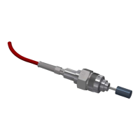
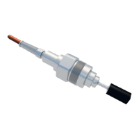
Sensor
Serial number: ……………………………
Interface box
Serial number: ……………………………
Model: ……………………………………
6.2 CONDITIONS FOR CORRECT WORKING OF THE VISCOSENSE
®
3 SENSOR
The flow is recommended to be in-between the maximum and minimum fluid flow rate as mentioned
in chapter 21.1.
The ViscoSense
®
3 housing should be placed in such a way, that no air can be trapped in the housing.
This can easily happen if the inner diameter of the piping is smaller than the inner diameter of the
ViscoSense
®
3 housing, if it has been installed horizontally.
If the inner diameter of the piping is smaller than the inner diameter of the ViscoSense
®
3 housing, the
transitions between the two diameters should be tapered. The inner diameter of the ViscoSense
®
3
housing should not be smaller than the piping.
The fluid should be homogenous.
It should not contain any air bubbles or foam.
THE FLUID SHOULD NOT CONTAIN ANY CHEMICALS OR SOLID PARTICALS THAT
CAN DAMAGE THE DLC COATING
THE FUEL SHOULD BE IN COMPLIANCE WITH ISO 8217:2010
(SPECIFICATIONS OF MARINE FUELS)