EasyManua.ls Logo

VAF instruments Viscosense 3 - User Manual

VAF instruments Viscosense 3
42 pages
Print Icon
To Next Page IconTo Next Page
Loading...
Technical Manual
Instructions for installation,
operation and maintenance
775
VISCOSENSE
®
3
Viscosity Sensor & Interface box
Valid for ViscoSense
®
3
Publication nr TIB-775-GB-0517
Supersedes TIB-775-GB-1216

Table of Contents

Questions and Answers

  • R
    Russell JohnstonAug 15, 2025
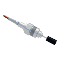
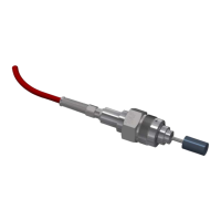
    What to do if viscosity output of VAF instruments Viscosense 3 Accessories is max range?
    • R
      Rebecca RomeroAug 15, 2025
      If the viscosity output is at the maximum range, it could be due to several reasons. The viscosity in the sensor housing might be higher than the maximum range, in which case you should heat up the fluid. Alternatively, the sensor might be damaged or fouled, so you should clean and inspect it. Also, check the diagnostic LED, mA signal, and range settings.
  • D
    dyerkristenAug 18, 2025
    What to do if viscosity output of VAF instruments Viscosense 3 Accessories is higher than expected?
    • C
      Christy WrightAug 18, 2025
      If the viscosity output is higher than expected, first consider that the actual viscosity might indeed be higher than expected. You should also check the mA signal and range settings. Another possible cause is a damaged or fouled sensor, so cleaning and inspecting the sensor is recommended.
  • D
    douglas29Aug 21, 2025
    What to do if viscosity output of VAF instruments Viscosense 3 is lower than expected?
    • D
      Deborah DixonAug 21, 2025
      If the viscosity output is lower than expected, it could be that the actual viscosity is lower than expected. You should also check the mA signal and range settings. Air entrapped in the fuel system could also be the cause, so venting the system is recommended.
  • D
    davidsimsAug 25, 2025
    Why is there no viscosity signal from VAF instruments Viscosense 3 Accessories?
    • S
      stewartamandaAug 25, 2025
      If there is no viscosity signal, it could be due to a lack of supply to the interface box, so check the supply. You should also check the fuses and electrical connections.
  • D
    davidowenAug 28, 2025
    Why is there no temperature signal from VAF instruments Viscosense 3 Accessories?
    • C
      Christopher JohnsonAug 28, 2025
      If there is no temperature signal, it could be because there is no supply to the interface box; therefore, you should check the supply. Also, check the fuses and electrical connections.
  • S
    Shawn RobinsonAug 30, 2025
    What causes mA output signal issues in VAF instruments Viscosense 3?
    • S
      Sean FoleyAug 30, 2025
      mA output signal issues can be caused by air entrapped in the fuel system. To resolve this, vent the system.
  • J
    Jessica JohnsSep 2, 2025
    What to do if set point is reached very slowly after initial exceeding in VAF instruments Viscosense 3 Accessories?
    • J
      Joseph PierceSep 2, 2025
      If the set point is reached very slowly after initially exceeding, the Pb may be too high. Decrease Pb.
  • I
    itravisSep 5, 2025
    Why oscillating temperature with distinct initial overshot in VAF instruments Accessories?
    • C
      Corey TaylorSep 6, 2025
      Oscillating temperature with a distinct initial overshoot can occur if the Pb is too low. Increase Pb to resolve this.
  • R
    Richard CoxSep 8, 2025
    What causes high initial overshot followed by fading oscillation in VAF instruments Viscosense 3 Accessories?
    • B
      Brian PotterSep 8, 2025
      A high initial overshoot followed by fading oscillation is caused by a Ti that is too low. Increase Ti.
  • J
    jeremyhernandezSep 12, 2025
    Why the set value is reached very slowly without overshooting in VAF instruments Viscosense 3?
    • J
      Jacob TownsendSep 12, 2025
      If the set value is reached very slowly without overshooting, the Ti may be too high. Decrease Ti.

Summary

1. PREFACE

1.1 GENERAL

General information about the manual, product, and VAF Instruments contact details.

1.2 SYMBOLS

Explains warning, caution, and information symbols used in the manual.

1.3 COPYRIGHT

States copyright and disclaims liability for errors or damages.

2. SYSTEM DESCRIPTION

2.1 SYSTEM DESCRIPTION

Describes the ViscoSense®3 system's application in fuel oil treatment for viscosity control.

2.2 SYSTEM COMPONENTS

Details the ViscoSense®3 system components: sensor, housing, and interface box.

2.3 PRINCIPLE OF OPERATION

Explains the sensor's torsion pendulum principle and viscosity measurement method.

3. TECHNICAL SPECIFICATION

3.1 SENSOR

Lists technical specifications for the ViscoSense®3 sensor, including range, accuracy, and material.

3.2 SENSOR HOUSING

Specifies material, flange connections, pressure rating, and weight for the sensor housing.

3.3 INTERFACE BOX

Details technical specifications for the ViscoSense®3 interface box, including supply voltage and outputs.

4. SAFETY INSTRUCTIONS

4.1 SAFETY PRECAUTIONS

Provides essential safety precautions for installation and operation personnel.

5. UNPACKING

6. INSTALLATION

6.1 TO RECORD NAMEPLATE DATA

Instructions to record critical nameplate data for identification and service.

6.2 CONDITIONS FOR CORRECT WORKING OF THE VISCOSENSE3 SENSOR

Specifies optimal fluid flow conditions and properties for sensor accuracy.

6.3 GENERAL INSTALLATION RECOMMENDATIONS

General advice for mounting, environment, and handling of the ViscoSense®3 system.

6.4 MECHANICAL INSTALLATION

Procedures for the physical installation of the ViscoSense®3 sensor and interface box.

6.4.1 ViscoSense3 interface box

Guidelines for selecting a suitable location and mounting the interface box.

6.4.2 ViscoSense3 housing

Procedures for installing the sensor housing, including piping support and vibration prevention.

6.4.3 To assemble ViscoSense3 sensor

Step-by-step guide for assembling the sensor into the housing, including torque specifications.

6.5 ELECTRICAL INSTALLATION

Instructions for providing power and connecting output signals to the interface box.

6.6 CONNECTION OF SENSOR TO INTERFACE BOX

Details wiring connections between the sensor and the interface box terminals.

6.7 INSTALLATION CHECKLIST VERSION 1.0

A checklist to verify all installation steps are completed correctly.

7. OPERATING INSTRUCTIONS

7.1 INITIAL START-UP

Guide for the initial start-up process using diesel oil before switching to HFO.

7.2 SHUT-DOWN ON HEAVY FUEL OIL

Instructions for shutting down the system when using heavy fuel oil.

7.3 SHUT-DOWN ON DIESEL OIL

No special actions required for shutting down on diesel oil.

7.4 ROUTINE START-UP

Procedure for routine start-up of the ViscoSense®3 system.

8. MAINTENANCE

8.1 ROUTINE MAINTENANCE

Outlines routine maintenance for the interface box under normal conditions.

8.2 TO CLEAN THE VISCOSENSE3 SENSOR

Procedures for safely cleaning the ViscoSense®3 sensor and its housing.

8.2.1 General procedure

Detailed steps for safely cleaning the ViscoSense®3 sensor and its housing.

9. REPAIR OR REPLACEMENT

9.1 REPAIR

States that sensor and interface box are not field-repairable and require exchange or return.

9.2 REPLACEMENT

Guidance on replacing components and using the SD card for settings.

9.3 PROCEDURE FOR USING THE MICRO SD CARD

Steps for inserting and using the micro SD card to upload sensor settings.

10. TAKE OUT OF SERVICE

11. REMOVAL AND STORAGE OF EQUIPMENT

12. MALFUNCTION AND SEND FOR REPAIR

13. ENVIRONMENT

14. DISPOSAL

15. TROUBLE SHOOTING

15.1 DISCONNECTION THE SENSOR

Explains sensor disconnection and warns against tampering with the sensor itself.

15.2 GENERAL TROUBLE SHOOTING

Covers common problems like no signal, and provides troubleshooting steps.

15.3 PI SETTING ERRORS (FOR ADDITIONAL VISCOSITY CONTROLLER)

Addresses issues with PI controller settings affecting temperature stability.

15.4 HOW TO TAKE A HFO SAMPLE FOR ANALYSIS

Detailed procedure for taking a High Fuel Oil sample for laboratory analysis.

15.5 DIAGNOSTIC INFORMATION

Explains system diagnostic codes and symbols displayed on the 7-segment LED.

16. CERTIFICATES

17. DRAWINGS

17.1 VISCOSENSE3 SENSOR AND SENSOR HOUSING

Technical drawings showing dimensions of the ViscoSense®3 sensor and housing.

17.2 VISCOSENSE3 INTERFACE BOX

Technical drawings and dimensions of the ViscoSense®3 interface box.

18. ABBREVIATIONS

19. PARTS LISTS

19.1 VISCOSENSE3 SENSOR

Lists spare parts for the ViscoSense®3 sensor, including part numbers.

20. WARRANTY CONDITIONS

21. ENCLOSURE

21.1 RECOMMENDATIONS FOR A GOOD WORKING BOOSTER UNIT

Provides recommendations for optimizing the performance of a booster unit.

VAF instruments Viscosense 3 Specifications

General IconGeneral
BrandVAF instruments
ModelViscosense 3
CategoryAccessories
LanguageEnglish

Related product manuals