17
6.7 INSTALLATION CHECKLIST VERSION 1.0
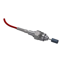
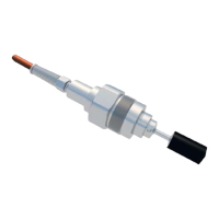
ViscoSense
Sensor:
Yes No
The ViscoSense
®
housing has been installed according the below set-up.
(Mark what is correct)
Capacity circulation fuel pomp _________ m3/h
Does the ViscoSense® housing size match the capacity circulation fuel pomp?
DN50 max. 20m3/h
DN65 max. 34m3/h
DN80 max. 51m3/h
DN100 max. 80m3/h
Has the ViscoSense
housing been installed correct according the fuel flow direction?
Has the inlet and outlet piping sufficiently been supported (as per 6.4.2)?
Have fuel pressure dampers been installed at the engine?
Is a pressure regulating valve installed within the fuel system ?
Is an air pocket present in the mixing tank?
Have isolating and bypass valves been installed at the ViscoSense
sensor?
Has the ViscoSense
®
interface box been installed away from the heater?
The ambient temperature at the ViscoSense
interface box is not higher than 55⁰C?