6
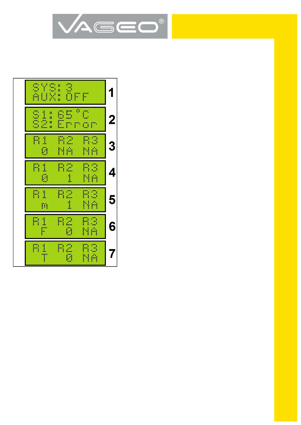
Symbolisms on the Screen:
FIGURE 3
<< AUX: OFF or ON >> as example on the screen 1,
shows the state of the controller checks whether or not
the auxiliary source for DHW applications 2 & 3.
<< Error >> like the example on the screen 2 means
damage to the sensor.
<< 0 >> below relay symbol as in the example screen 3
shows that the contact exists and is open.
<< NA >> under relay symbol indicates that the contact
does not exist.
<< 1 >> under relay symbol like the example on the screen 4
shows that the contact exists and that it is closed.
<< M >> below relay symbol as in the example on the
screen 5, shows that the contact exists, but the tem-
perature sensor collectors << S1 >> is below the value
of the parameter << MCT >> low temperature collector
(See . p.8 TABLE 1).
<< F >> under relay symbol like the example on the
screen 6 shows that the contact exists but the tempera-
ture sensor collectors << S1 >> is equal to or below the
value of the parameter << FPC >> frost protection (see
p.8 TABLE 1).
<< T >> under relay symbol like the example on the screen 7 shows that the contact exists
but the temperature sensor collectors << S1 >> has reached the value of the parameter <<
MTC >> overheat protection panel (See TABLE 1 p.8).
 Loading...