7Installation instructions Mixer module VR 60 0020020171_02
5.3 Setting the Bus address
Communication within the system takes place via an
eBus. To ensure flawless communication between all the
components it is necessary to allocate a unique address
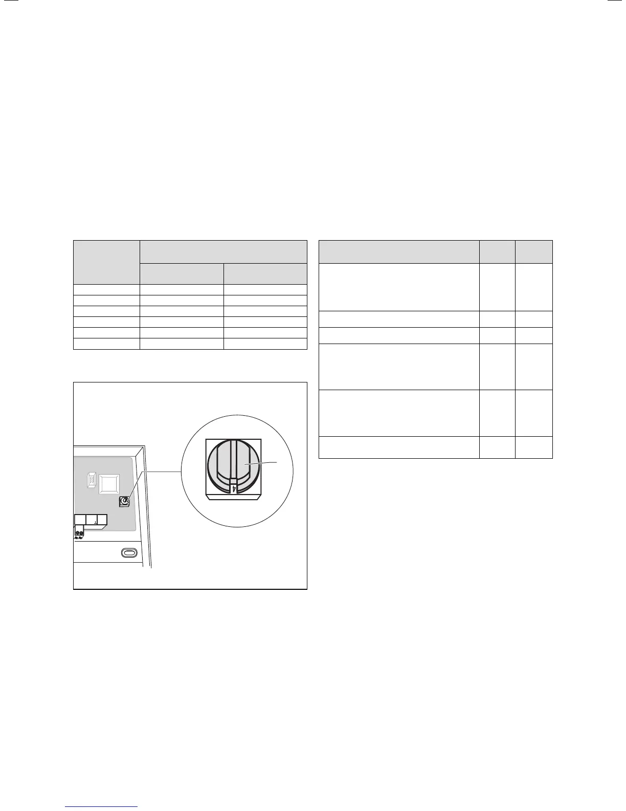
to the individual mixer circuit. To do this set the value 4,
6, 8, 10, 12 or 14 on the address switch (Fig. 5.3 (3)) de-
pending upon whether the VR 60 mixer module has al-
ready been integrated in the system.
Addresses 0 to 3 are used by the system circuits in the
auroMATIC 620 and VRC 630 controllers or the Vaillant
geoTHERM VW.. .../2 heat pump and are not therefore
available for addressing.
Addresses to be
set
Assignment in the auroMATIC 620/
VRC 630
Heating circuit a Heating circuit b
4 HK 4 HK 5
6 HK 6 HK 7
8 HK 8 HK 9
10 HK 10 HK 11
12 HK 12 HK 13
14 HK 14 HK 15
Table 5.1 Bus addresses to be set
AF 0
AF
2 1
VFb
3
Fig. 5.3 Setting the bus address
After connecting the electrical installation:
• Fix all cables with the accompanying cable clamps
(Fig. 4.2 (2)).
• Insert the casing cover back into the hinges and hinge
the casing cover back up into position.
• Screw the casing cover in position in accordance with
Fig. 4.1.
6 Start-up
Starting up the VR 60 mixer module is carried out in
conjunction with starting up the auroMATIC 620 or
VRC 630 controller or the Vaillant geoTHERM VW.. .../2
heat pump. To do this, proceed in accordance with the
instructions in the manual for the
auroMATIC 620 or VRC 630 controller or the Vaillant
geoTHERM VW.. .../2 heat pump.
7 Technical data
Unit VR 60
Operating voltage
Power consumption
Contact load of the output relays (max.)
Maximum total current
V
VA
A
A
230
2
2
4
Maximum permissible ambient temperature °C 40
Operating voltage sensor V 5
Minimum cross-section of the sensor cables,
eBUS cables
Minimum cross-section of power cable
(rigid cable, NYM)
mm2
mm
2
0.75
1.5
Dimensions of wall mounting base
Height
Width
Depth
mm
mm
mm
174
272
52
Level of protection
Protection rating for regulator
IP 20
II
Table 7.1 Technical data
Electrical installation 5
Start-up 6
Technical data 7
 Loading...