User's Guide _______________________________________________________________________
16 ___________________________________________________________________ M211399EN-G
1201-006
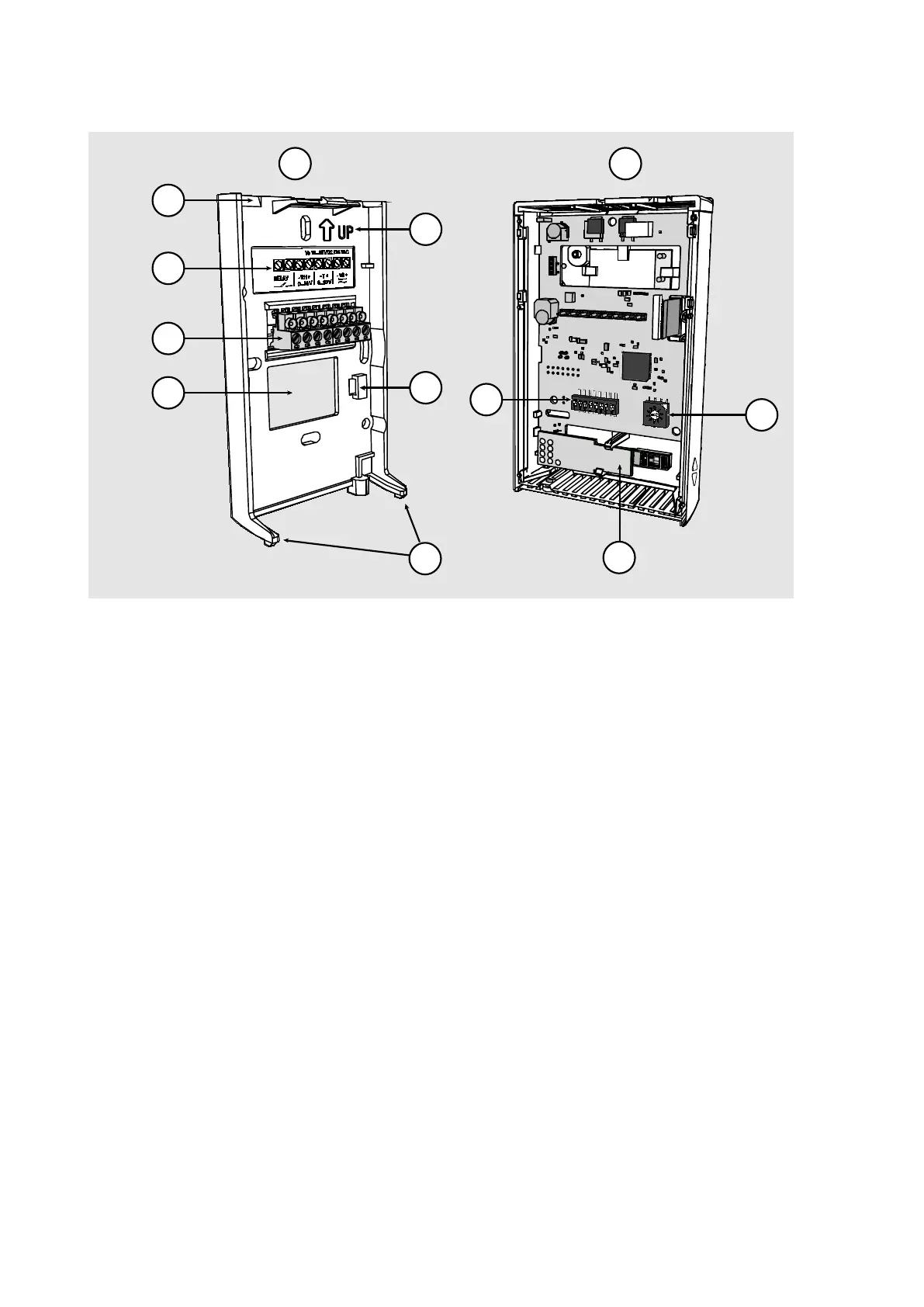
Figure 4 Transmitter Parts – Inside (Analog Output Models)
Opening for cable (wiring from top)
Opening for cable (wiring from behind)
Orientation arrow – should point up after the mounting base has
been installed.
Place for zip tie (for cable strain relief)
DIP switches for common configuration options; see section DIP
Switches of Analog Output Models on page 20.
Rotary switch for relay setpoint (only for models with relay);
see section Relay Configuration in DIP Mode on page 21.
HTM10 module with HUMICAP
®
sensor (HMW models) or
TM10 module (TMW models, measures temperature only).
Non-Me tric
Td
0...5V
Relay On
Relay High
Custom
Relay Set P oint
Metri c
RH
0...10V
Relay O
ff
Relay Low
DIP
2
3
4
5
11
10
6
7
1
9
8
12
 Loading...