User's Guide _______________________________________________________________________
8 _____________________________________________________________________M210374en-A
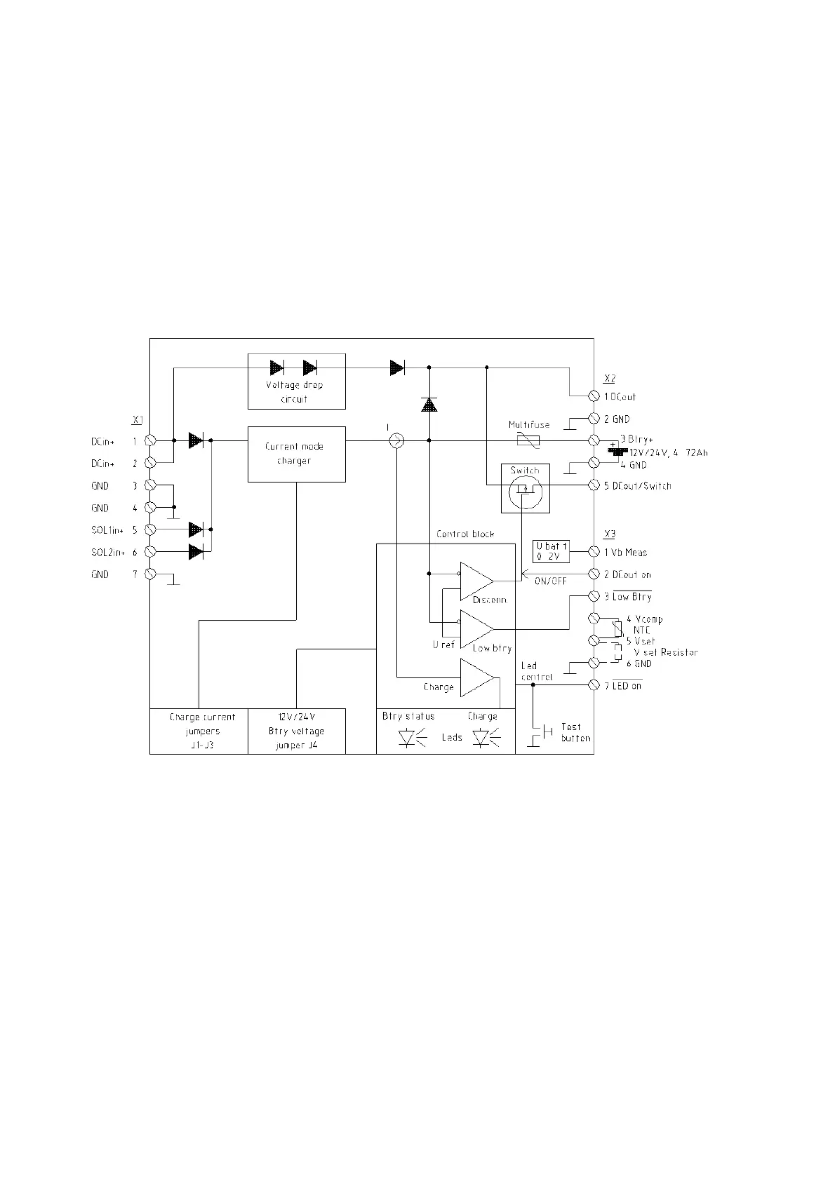
The load is normally connected to the DCout/Switch terminal (X2/5),
which provides deep discharge protection for the battery. When the
battery voltage drops below deep-discharge limit and there is no
power available from the DCin inputs (X1/1,2), the output current is
automatically switched off. The DCout terminal (X2/1) does not have
this function, but instead it would fully discharge the battery.
Therefore, it should be used only for those systems having an input
shutdown function of their own, with a suitable threshold voltage
(approx. 10 V/20 V for 12 V/24 V systems, respectively).
0303-053
Figure 1 Functional Block Diagram of QBR101
In normal 12 V operation the input power (to X1/1 and 2) is taken
from an off-line SMPS with a 15.5 to 16 V output voltage. Inside the
QBR101 the input voltage is applied both to the Battery Charger and
via the Voltage Drop Circuit to the output terminals DCout (X2/1) and
DCout/Switch (X2/5). The Voltage Drop Circuit makes an intentional
drop of 0.7 to 1.5 V (depending on the load current), making the
DCoutput voltage suitable for those system components withstanding
maximum 15.5 V operational voltage.