User's Guide _______________________________________________________________________
14 ____________________________________________________________________M210374en-A
The Battery Status LED has three states. It is green when the battery
voltage is OK, orange when the battery voltage is low (< 11.5 V with
12 V systems or < 23 V with 24 V systems), and red when the battery
voltage is below the deep discharge limit (10 V or 20 V). In the latter
case also the load at the DCout/Switch terminal is automatically
disconnected.
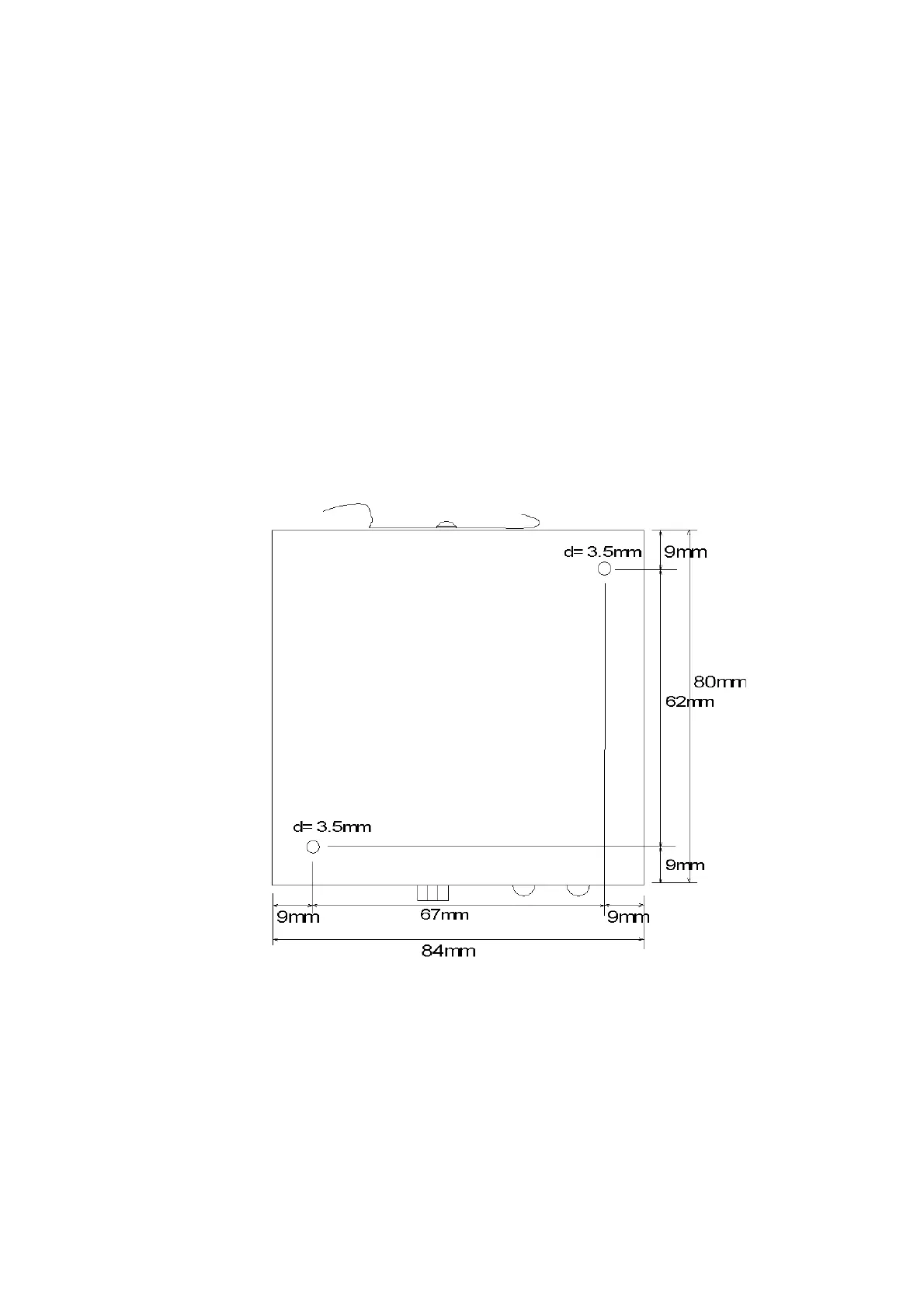
Mechanical Installation
The QBR101 can be installed to 35 mm DIN-rail using rail clip on the
rear. Alternatively it can be mounted to a wall or equivalent surface
with M3 screws on the bottom. The maximum allowable length of the
screw threads is 6 mm. The physical dimensions of the QBR101 and
the location of the installation holes are illustrated in Figure 3 below.
0303-055
Figure 3 Installation Hole Dimensions
 Loading...