User's Guide _______________________________________________________________________
12 ____________________________________________________________________M210374en-A
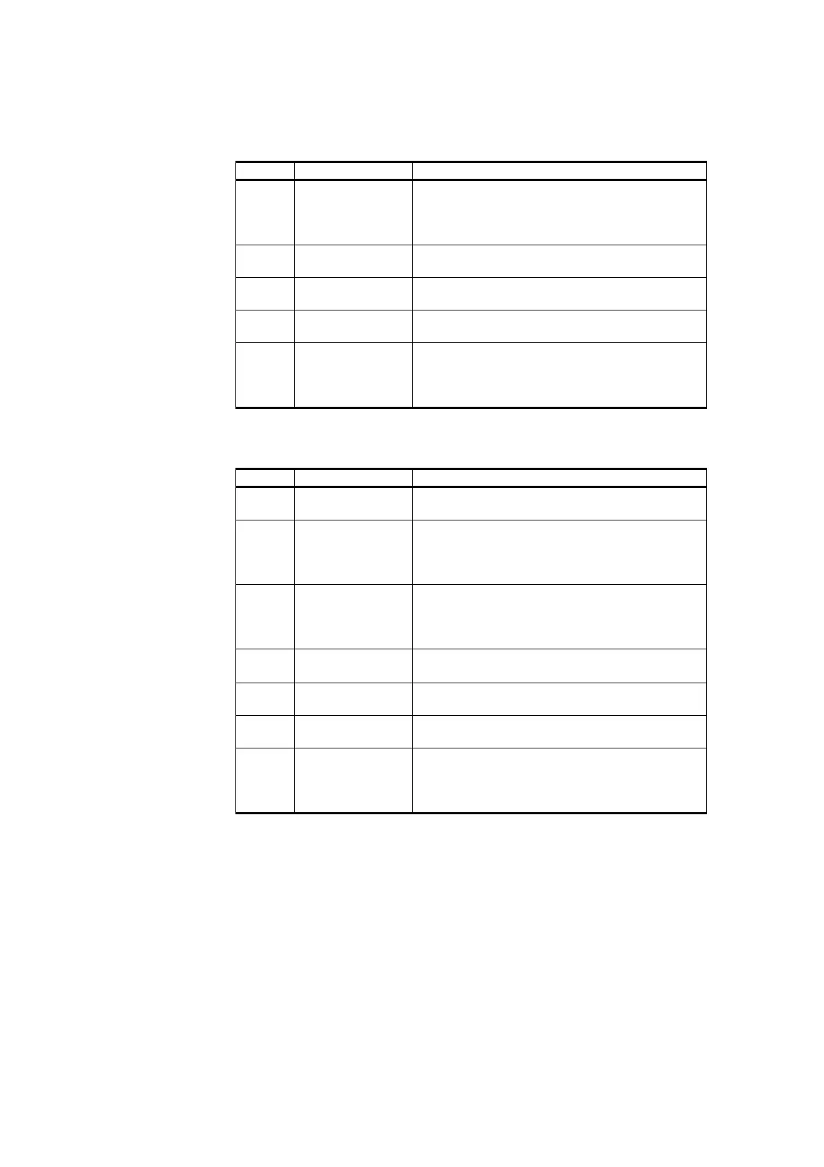
Table 3 Output Connector X2
Pin No Terminal Name Notes
1 Dcout Output terminal for straight DC-output. This
output is always live, when DCin+ voltage is
connected or when charge is left in the
battery.
2 GND Ground terminal for DCout and DCout/Switch
outputs.
3 Btry+ Terminal for + (positive) pole of the Backup
Battery.
4 GND Terminal for - (negative) pole of the Backup
Battery.
5 DCout/Switch Output terminal for Switched DC-output. This
output is controlled with the DCout ON
terminal and Battery deep discharge circuit.
This terminal is not overload protected.
Table 4 Control Connector X3
Pin No Terminal Name Notes
1 Vb Meas Measuring terminal for Battery Voltage. Value
of Vb Meas voltage is between 0…2 V.
2 DCout ON Remote on/off control input for DCout/Switch
output. DCout ON > 2,5 V enables
DCout/Switch. DCout ON < 2 V or floating
disables DCout/Switch.
3 Low Btry Low Btry Alarm output. Low (<0.7V) when
Battery voltage < 11.5V with 12V systems or <
23.0 V with 24 V systems. Else high
(via 164 kohm to DCout/Switch voltage).
4Vcomp
NTC resistor (10k at 25 °C) is connected
between terminals Vcomp and Vset.
5 Vset External Charging Voltage Selection Resistor
is connected between Vset and GND.
6 GND Ground terminal for Vb Meas, Vset, and LED
ON terminals.
7 LED ON Control terminal for Battery Status LED
(intended for external TEST switch). The LED
is lit when LED ON terminal is connected to
the ground.
 Loading...