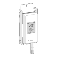
RFL100 parts
Figure 11 Front and display
1 Service port connection indicator
2 Battery level indicator
3 Currently measured values
4 Connection indicators
5 Status LED. Blinks green for normal
operation, red for error or alarm.
6 Signal strength of access point
connection
7 Alarm indicators. Alarms are
configured in viewLinc Enterprise
Server software.
8 Detachable probe, or extension cable
Figure 12 Under the silicone plug
1 Service port (micro-USB). If using
external power supply, connect it here.
2 Info button. Push to enable info mode
for 1 hour, and again to end the info
mode. Info mode cycles through
information screens, and also enables
faster wireless scanning.
See RFL100 User Guide (M211861EN) for more information on service port and info
mode.
21
ENGLISH

 Loading...