User's Guide ______________________________________________________________________
8 ___________________________________________________________________ M210310EN-B
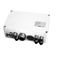
0210-014
Figure 1 Inside TERMBOX-1212
The following numbers refer to Figure 1 above:
1 =
Cover screws
2 = AC power overvoltage protector
3 = Fuse
4 = AC power connections
5 = Signal line connections/protectors
6 = Mounting screws (located at the bottom)
TERMBOX Models
There are three TERMBOX models available. The AC block is the same
in each TERMBOX model, however the signal line connections differ.
For details on the different TERMBOX models, see Table 1 below.
Table 1
TERMBOX Models
Code Signal Connection
TERMBOX-9000 Connector block with 90 V gas tube arresters
TERMBOX-1200 One signal line protector, 12 V
TERMBOX-1212 Two signal line protectors, 12 V
 Loading...