EasyManua.ls Logo

VALCO MELTON EC8 User Manual

Default Icon
123 pages
To Next Page IconTo Next Page
Page #1 background imageLoading...
Page #1 background image
Declaration of conformity
The product:
Model nº:
Serial nº:
Year of manufacture:
Described in the enclosed documentation is in conformity with:
Directive 2006/42/EC of 29 December 2009 which replaces Directive
98/37/EC of 22 June 1998 on the approximation of the laws of the
Member States relating to machinery, which regroups Directives
89/392/EEC of 14 June 1989, 91/368/EEC of 20 June 1991, 93/44/EEC of
14 June 1993 and 93/68/EEC of 22 July 1993. Directive applicable to
standard EN ISO 12100-1 and EN ISO 12100-2, related to safety of
machinery; standard EN ISO 14121-1 and EN ISO 14121-2, related to
safety of machinery. Risk assessment; standard UNE-EN 60204-1, related
to safety of machinery. Electrical equipment of machines; standard UNE-
EN 61310-1, UNE-EN 61310-2 and UNE-EN 61310-3, related to safety of
machinery. Indication, marking and actuation.
Directive 2006/95/CE of 12 December 2006 which replaces Directive
73/23/EEC of 19 February 1973 on electrical equipment.
Directive 2004/108/EC of 20 July 2007 which replaces Directive
89/336/EEC of 3 May 1989 on Electromagnetic Compatibility.
Directive 93/68/EEC of 22 July 1993 which modifies 73/23/EEC and
Directive 89/336/EEC.
Hoses are factory tested at 100 bars and at 22C.
within the scope of the specifications indicated in the chapter describing the equipment
with a B1 risk level. Since it is intended to form part of a set of machines which, to obtain
a result, are arranged and connected to perform together, it cannot be operated until the
set of machines has been declared in conformity with the applicable Directives by the
person responsible for the final assembly.
Orcoyen, on : / /
Signed.:______________________
Gonzalo Marco, Managing director.
Polígono Industrial Agustinos, calle G, nave D-34
Tel.: +34.948.321.580 Fax: +34.948.326.584
31160 ORCOYEN (Navarra) SPAIN

Other manuals for VALCO MELTON EC8

Question and Answer IconNeed help?

Do you have a question about the VALCO MELTON EC8 and is the answer not in the manual?

VALCO MELTON EC8 Specifications

General IconGeneral
TypeDispenser
ModelEC8
Power Supply220-240V AC, 50/60Hz
MaterialSteel
Safety FeaturesOverheat protection

Summary

SAFETY INSTRUCTIONS

1.1. SYMBOLS AND TERMS

Explains safety symbols, warnings, and terms used in the manual.

1.2. PURPOSE

Details the intended use and application of the equipment.

1.3. FIRST AID

Provides essential first aid procedures for accidents and injuries.

DESCRIPTION

2.1. INTRODUCTION

Offers a general introduction to the machine's function and design.

2.2. MAIN PARTS

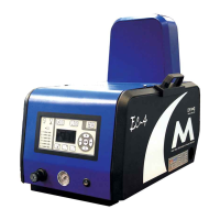
Identifies and describes the primary physical components of the equipment.

2.3. TECHNICAL CHARACTERISTICS

Lists key technical specifications, performance data, and capabilities.

2.4. DIMENSIONS

Provides the physical dimensions of the equipment for installation planning.

2.4.2. GENERAL DIMENSIONS WITH VACUUM FEEDING (MODEL TYPE C)

Specific dimensions for model type C with vacuum feeding.

MACHINE INSTALLATION

3.1. INTRODUCTION

Introduces the process of installing the machine correctly.

3.2. TRANSPORT

Details procedures and precautions for transporting the equipment safely.

3.3. INSTALLATION REQUIREMENTS

Outlines the necessary conditions and space for proper machine installation.

3.4. MECHANICAL INSTALLATION

Covers the steps for physically connecting hoses and components.

3.5. PNEUMATIC INSTALLATION

Explains how to connect the pneumatic air supply to the unit.

3.6. ELECTRICAL INSTALLATION

Describes the procedures for connecting the machine to the electrical power supply.

MACHINE ADJUSTMENT

4.1. INTRODUCTION

Explains adjustments needed for proper and safe machine operation.

4.2. TEMPERATURE CONTROL

Details how to set and manage the operating temperatures for different zones.

4.3. OTHER ADJUSTMENT

Covers various other settings and parameters for fine-tuning the machine.

OPERATION

5.1 START THE UNIT

Step-by-step guide on how to power up and start the machine.

5.2 TEMPERATURE

How to view and manage the current and setpoint temperatures.

5.3 CLOCK ON/OFF

Instructions for enabling or disabling the internal clock for scheduled operations.

5.4 SETBACK

Explains how to reduce temperatures during periods of inactivity.

5.5 POT FILL EXTERNAL LOW LEVEL DETECTION

Procedure for monitoring and filling an external pot based on level.

5.6 HOPPER FEEDER INTERNAL LOW LEVEL DETECTION

Details automatic refilling of the tank using the hopper feeder.

5.7 BEACON ALARM

Configuration of visual or audio alarms for fault conditions.

5.8 EXTERNAL INPUT

How to use external inputs for functions like Setback Timeout reset.

5.9 FILLING THE TANK

Safe procedures for filling the machine's adhesive tank.

5.10 STOPS

Instructions for stopping the pump and powering down the unit.

MAINTENANCE

6.1. INTRODUCTION

Introduces maintenance procedures for safe operation and longevity.

6.2. MAINTENANCE RECOMMENDATIONS

Outlines recommended maintenance tasks and their frequencies.

6.3. MAINTENANCE PROCESSES

Provides detailed steps for common maintenance tasks like cleaning.

TROUBLESHOOTING THE EQUIPMENT

7.1. INTRODUCTION

Introduces common equipment faults and how to resolve them.

7.2. MECHANICAL FAULTS

Guides on diagnosing and fixing mechanical issues with the machine.

7.3. ELÉCTRICAL FAULTS

Guides on diagnosing and fixing electrical faults within the equipment.

7.4. ADHESIVE APPLICATION PROBLEMS

Addresses common issues related to adhesive application quality and flow.

EQUIPMENT REPAIR GUIDE

8.1. INTRODUCTION

Explains procedures for dismantling and replacing machine components.

8.2. CHANGING THE FILTER

Step-by-step instructions for replacing the equipment's filter unit.

8.3. REPAIRING THE MANIFOLD

Guidance on how to repair or address issues with the manifold.

8.4. REPAIRING THE PNEUMATIC PUMP UNIT

Detailed procedures for repairing the pneumatic pump system.

8.5. CLEANING VALVES

Instructions for cleaning various valves within the system.

8.6. REPAIRING ELECTRIC COMPONENTS

Procedures for repairing or replacing electrical components.

8.7. REPAIRING VACUUM FEEDER

Steps for repairing the vacuum feeder system.

LOG SHEETS

Related product manuals