5
Connecting Arrangements
• Proceed to Figure 3 for stand-alone ringing
connections.
• Proceed to Figure 4 for ringing over paging
connections.
• Proceed to Figure 5 for telephone system
providing a dry contact closure for common
audible signaling.
WIRING INSTRUCTIONS:
Place a check by each step as it is completed.
__ 1. Connect Tip of the first Central Office Line or
PABX station number to the V-9936A pin 1
(C. O. 1 Tip).
__ 2. Connect Ring of the first line or station to
pin 16 (C. O. 1 Ring).
__ 3. Connect Tip of Line 2 to pin 2 and connect
Ring of the line to pin 17.
__ 4. Connect Tip of Line 3 to pin 3 and connect
Ring of the line to pin 18.
__ 5. Connect Tip of Line 4 to pin 4 and connect
Ring of the line to pin 19.
__ 6. Connect Tip of Line 5 to pin 5 and connect
Ring of the line to pin 20.
__ 7. Connect Tip of Line 6 to pin 6 and connect
Ring of the line to pin 21.
__ 8. If using multiple V-9936A's:
__ (a) Connect a group of 6 lines or station
numbers to each V-9936A as in steps 1-7.
__ (b) Connect wire from pin 8 (Expansion) of the
main unit to pin 8 of each additional unit.
9. If using Valcom speakers for signaling:
__ (a) Connect Tip of speaker to pin 11.
__ (b) Connect Ring of speaker to pin 26.
__ (c) If using one-way amplified speaker
assemblies:
__ (1) Connect the -24VDC speaker lead to
V-9936A pin 10.
__ (2) Connect the Ground speaker lead to pin
25.
__ (d) Set the speaker select switch to Hi Z if
using 45 Ohm talkback speakers or set it to
Lo Z if using one-way amplified speakers.
10. If using Bells or other devices for signaling:
__ (a) Connect one side of the output of an
appropriate power source to pin 12 of the
V-9936A.
__ (b) Connect the other side of the power source
to one of the input terminals on your
signaling device.
__ (c) Connect from pin 27 of the V-9936A to the
other input terminal of your signaling
device.
__ (d) Consult the information supplied with the
signaling device for additional information.
__ 11. If adding a night switch, connect it to pins 9
and 24.
__ 12. Plug in power supply (See the Power
Connection section).
__ 13. If using speakers for signaling, dial a line
connected to the V-9936A. When it starts
ringing, adjust the V-9936A volume control
to the desired level.
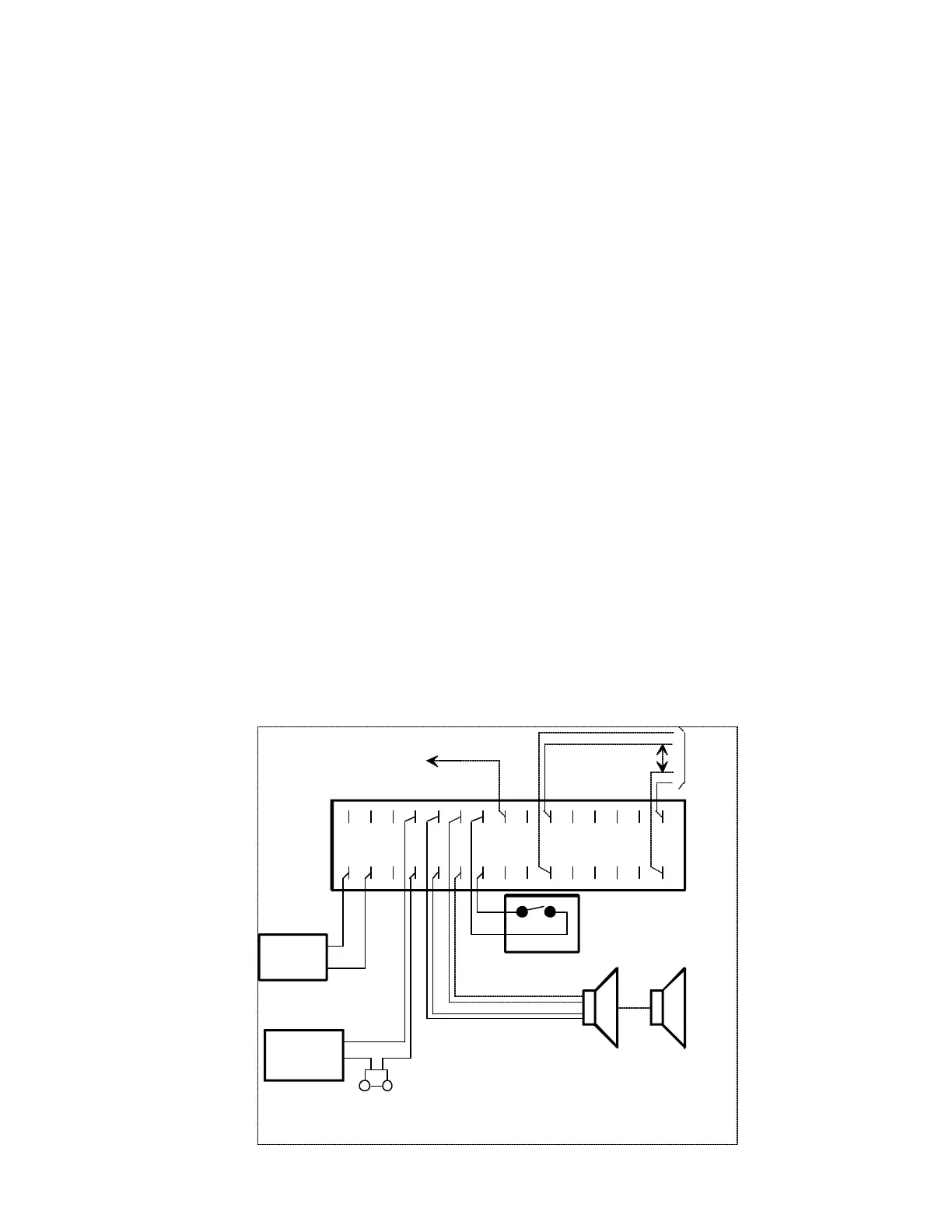
15 14 13 12 11 10 9
8 7 6 5 4 3 2 1
30 29 28 27 26 25 24 23 22 21 20 19 18 17 16
24VDC
POWER
SUPPLY
-
+
RING SUPPLY
LOUD BELL
NIGHT SWITCH
SPEAKERS
V-9936A
TO PIN 8 OF
ALL ADDITIONAL
V-9936A's
6
1
Central
Office or
Station
Lines
FIGURE 3 - STAND-ALONE RINGING CONNECTIONS
 Loading...