11
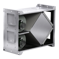
Energy Core Ventilator
HOA Troubleshooting
ERV Troubleshooting Guide
Symptoms Potential Issues Fix
Unit is NOT operating
¦ Loss of Input Power
¦ Incorrect wiring
¦ Green LED is not illuminated for Remote
ON
¦ No contact closure between Pins 1 & 2
of TB2 for Remote “ON”
¦
Check Breaker
¦
Check input power Wiring
¦
Validate correct Input Power to Terminal
Block TB1
¦
Validate a short between Pins 1 & 2 of
TB2 for Remote “ON”
¦
Validate Green L
ED is illuminated for
Remote ON
Energy Wheel Motor
does not turn ON
¦ No contact closure between Pins 1 & 2
of TB2 for Remote “ON”
¦ Validate Motor wiring to W5 and W6
(1/4”) Spade Faston tabs on ERV
Controller
¦
Validate Motor Wiring
¦
Validate Green LED on ERV Controller is
illuminated “ON”
¦
Energy Wheel is stuck and is not free.
Turn the energy recovery wheel by hand
to verify free operation
¦
Replace motor
A Motor does not
turn ON
¦ No contact closure between Pins 1 &
2 of TB2 for Remote “ON”
¦ Validate Motor wiring to W3 and W4
(1/4”) Spade Faston tabs on ERV
Controller
¦ Validate speed potentiometer is above
> 2.0Vdc
¦ Validate Motor Wiring
¦ Validate 0-10V Motor command Voltage
at Motor. Motor command voltage must
be> than 2.00V
¦ Validate Frost control is not activated.
Check SW1 Inlet/Outlet switch
B Motor does not
turn ON
¦ No contact closure between Pins 1 &
2 of TB2 for Remote “ON”
¦ Validate Motor wiring to W1 and W2
(1/4”) Spade Faston tabs on ERV
Controller
¦ Validate speed potentiometer is above
> 2.0Vdc
¦ Validate Motor Wiring
¦ Validate 0-10V Motor command Voltage
at Motor. Motor command voltage must
be> than 2.00V
¦ Validate Frost control is not activated
Check SW1 Inlet/Outlet switch
No Frost Control
¦ Validate Thermostat Wiring Pins 5 and 6
of TB2
¦ Validate Blue LED is Illuminated
¦ Inlet and Exhaust vents are swapped
simply slide SW1 switch on ERV PCB A
and B motors to reverse setting
¦ Validate Frost control is not
activated.
¦ Validate SW1 Inlet/Outlet switch is
set correctly.
¦ Validate Timers T1 and T2 for
correct settings.
No remote +24V
Sensor Power
¦ Check wiring to Pins 3 and 4 of TB2.
¦ Measure Voltage at Pins 3 and 4 of
TB2 for +24Vdc
¦ Check input power Wiring
¦ Validate correct Input Power to Terminal
Block TB1
¦ Remove wires at Pins 3 and 4 of TB2
and measure the voltage for +24Vdc. If
+24Vdc is measured, there is too much
current draw (sensor can be damaged or
drawing too much power) Check Breaker