8
Energy Core Ventilator
Before connecting power to the unit, read and
understand the following instructions and wiring
diagrams. Complete wiring diagrams are attached inside
the blower door of the unit.
All wiring should be done in accordance with the
National Electrical Code ANSI/NFPA 70 latest edition
and any local codes that may apply. In Canada,
wiring should be done in accordance with the
Canadian Electrical Code. The equipment must be
properlygrounded.
A
B
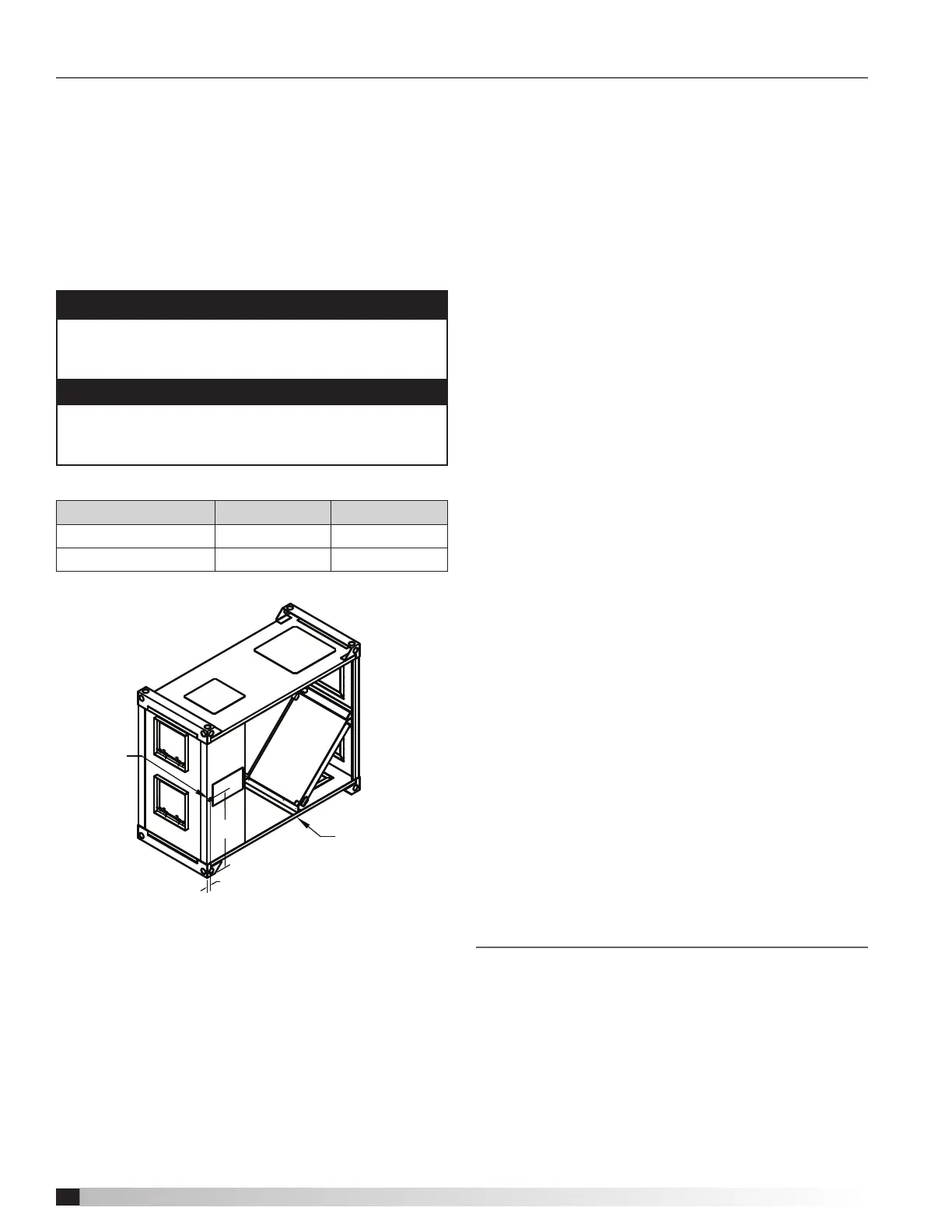
Electrical
Core, Filter, and
Blower Access
Sequence for Wiring Unit
1. The unit’s nameplate contains the voltage and total
amperage required. The wire supplying power to
the unit should be sized accordingly.
2. The main power line should be connected to the
appropriate terminal blocks.
Power may be routed to the unit through the
opening on the underside of the unit. The locations
for the opening are provided in the figure above.
3. Refer to the wiring diagrams in this manual or in the
unit for controlling the unit.
Electrical Connection Location
Model A B
Without disconnect
1 20.6
With disconnect
2.4 25.5
All dimensions are in inches.
CAUTION
If any of the original wire must be replaced, the
replacement wire must have a temperature rating of at
least 105ºC.
DANGER
High voltage electrical input is required for this
equipment. This work should be performed by a
qualified electrician.
Frost Control
Extremely cold outdoor air temperatures can cause
moisture condensation and frosting on the energy
recovery core. Frost Control is a selectable timer control
that will prevent frosting. Frost control uses a Therm-O-
Disc P/N: 314886 T-O-D 60T11 (L15-10F) mounted in
the outdoor air intake compartment. Thermo-O-Disc has
pre-set temperature of 5°F and uses the normally closed
contacts; contacts open on temperature rise. Use the
test procedure for troubleshooting.
Frost Control Test Procedure
1. Remove power from unit.
2. Jumper the temperature indicating Therm-O-Disc in
the unit control center. Therm-O-Disc has a pre-set
temperature of 5ºF.
3. Set the frost control timer scale for T1 and T2 to 5m.
Set the timer settings for T1 and T2 to 0.
4. Add power to the unit. Blower should cycle on for 5
minutes, then turn off for 5 minutes.
5. Remove power from unit and remove jumpers that
were placed. Re-set timer settings.
• T1 timer ON setting set to 5 for 30 minutes of wheel
on time.
• T2 timer OFF setting set to 0 for 5 minutes of wheel
off time.
Electrical Connections
Timer Settings:
T1 ON Timer T2 OFF Timer
0 = 5 MIIN 0 = 5 MlN (default)
1 = 10 MIN 1 = 10 MIN
2 = 15 MIN 2 = 15 MIN
3 = 20 MIN 3 = 20 MIN
4 = 25 MIN 4 = 25 MIN
5 = 30 MIN (default) 5 = 30 MIN
6 = 35 MIN 6 = 35 MIN
7 = 40 MIN 7 = 40 MIN
Control Components
Verify that all of the following parts and hardware
have been received prior to beginning installation.
Contact your local representative or the
manufacturer if replacement parts are required.
NOTE: Additional parts (provided by others) may
be required to complete the control installation,
including additional wiring and hardware for
mounting the control to the building structure.
NOTE: See following page for diagram of control
components.