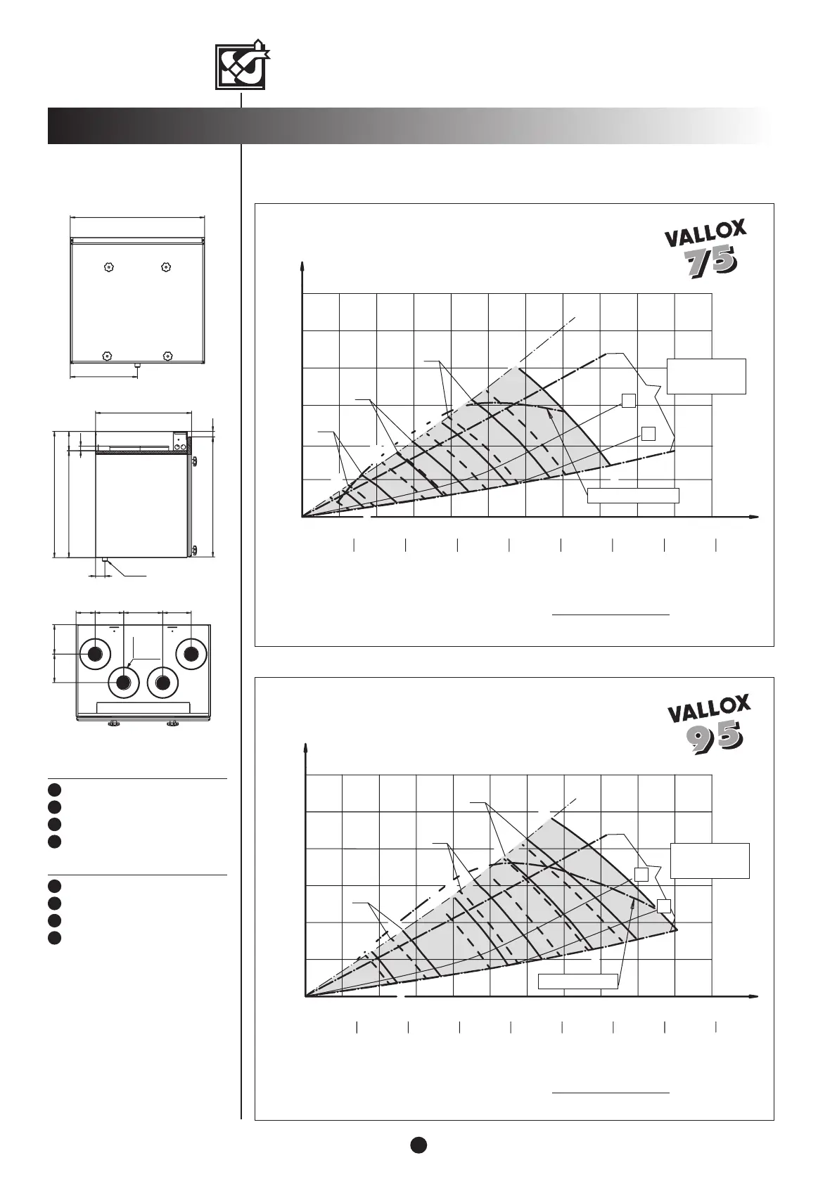
m
3
/h
10 20 30 40 50
Pa
100
60 70 80 90 100 110
E
E
E
E
S
S
S
S
1
2
3
0
50
150
200
250
300
4
1.1
2.1
3.1
dm
3
/s
50
100 150
200 250 300 350
400
SFP, kW (m
3
/s) 2,5
10 20 30 40 50
Pa
100
60 70 80 90 100 110
E
E
E
E
S
S
S
S
1
2
3
0
50
150
200
250
300
4
1.1
2.1
3.1
50 100 150 200 250 300 350 400 m
3
/h
dm
3
/s
SFP, kW (m
3
/s) 2,5
Volume flow rate
VALLOX 75/fan 105 W
VALLOX 95/Fan 180 W
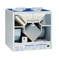
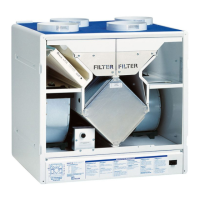
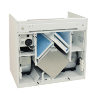
DUCT OUTLETS
Supply air to the dwelling
Extract air from the dwelling
Outdoor air to the unit
Exhaust air outside
4
3
2
1
Exhaust air outside
Outdoor air to the unit
Extract air from the dwelling
Supply air to the dwelling
4
3
2
1
VALLOX 75/95
2
2
Pressure loss in ducts. Total pressure
SFP (Specific Fan Power)
guideline value < 2.5 (kw/m
3
/s)
SFP=
Input power (total) (W)
Air flow (max) (dm
3
/s)
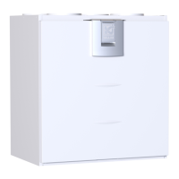
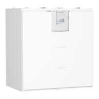
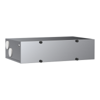
Dimensions and
duct outlets
R model
L model
R 1/2
19
403
-3.0
+0.0
23
504
530
82
448
39
282
564
1
2 3
4
Ø125 mm
4 kpl
80 120 163.5 120
123.5120
4
3
2
1
ED
SD
ED
SD
RECOMMENDED
OPERATING RANGE
Fan curves
E = Extract air curve
S = Supply air curve
SD and ED are examples of pressure
losses in supply and extract ducts
Volume flow rate
Air volumes and SFP
Pressure loss in ducts. Total pressure
SFP (Specific Fan Power)
guideline value < 2.5 (kw/m
3
/s)
SFP=
Input power (total) (W)
Air flow (max) (dm
3
/s)
RECOMMENDED
OPERATING RANGE
Fan curves
E = Extract air curve
S = Supply air curve
SD and ED are examples of pressure
losses in supply and extract ducts