Parts list VALLOX 75 VKL / VALLOX 95 VKL
Code Name Technical details Standard /
option
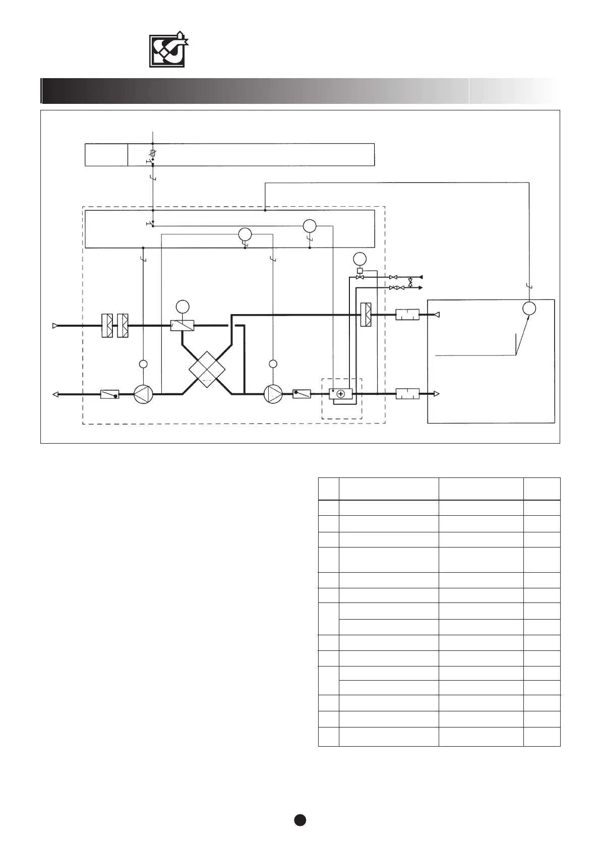
Description of operation for VALLOX 75/95VKL
Control of operation
Power supply to the unit is controlled with the 0/1 switch in the
distribution panel. There is also a maintenance / safety switch SS
inside the unit. It stops power supply when the door of the unit is
opened.
Fan speed adjustment
The operation of the fans S and E of the unit is controlled with a
separate control centre HS, located in the ventilation zone, or with
a cooker hood.
Supply air temperature
Self-actuated control valve V1 controls the operation of the postheating
radiator R, maintaining the temperature of supply air going out from
the unit at the setpoint value.
Heat recovery bypass
Summer-time bypass of the heat recovery cell HR is done manually
by turning the HR damper H in the bypass position for the summer.
Heat recovery defrosting
The defrost thermostat T1 of the HR cell keeps stopping the supply air
fan S, thereby preventing the risk of the freezing in the HR cell. The
fan starts automatically as soon as the risk of freezing has passed.
The threshold temperature of the risk of freezing can be set at the
thermostat T1.
Water radiator defrosting
The defrost thermostat T2 of the post-heating radiator R stops the unit
when the temperature of water radiator goes below the threshold
value, preventing the risk of freezing in the water radiator. This also
causes self-actuated one-way dampers SP to close, preventing the
flow of outdoor air to the unit. The unit starts automatically as soon
as the risk of freezing has passed. The threshold temperature of
freezing risk can be set at thermostat T2.
VALLOX 75/95
8
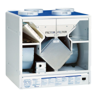
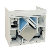
CONTROL DIAGRAM AND DESCRIPTION OF OPERATION FOR VALLOX 75/95 VKL WATER RADIATOR
G3 Filter, extract air and supply air G3 Standard
F7 Fine filter, supply air at least F7 F7 Standard
H HR bypass damper Manual Standard
HS Speed adjustment Separate control centre Option
or cooker hood
R Post-heating radiator Water radiator 0.5 kW Standard
HR Heat recovery cell Efficiency approx. 60% Standard
S Supply air fan / VALLOX 75 105 W, 65 l/s (50 Pa) Standard
Supply air fan / VALLOX 95 180 W, 80 l/s (75 Pa) Standard
SS Service switch Door switch Standard
T1 Regulating thermostat 0…40 °C Standard
E Extract air fan / VALLOX 75 105 W, 75 l/s (80 Pa) Standard
Extract air fan / VALLOX 95 180 W, 95 l/s (100 Pa) Standard
V1 Control valve Self-actuated + 5…21 °C Standard
T2 Water radiator defrost thermostat Factory setting +5 °C Standard
SP One-way damper, 2 pcs Air flow operated Standard
G3
G3
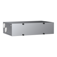
SILENCER
SILENCER
H
F7
E
S
R
HEAT RECOVERYCELL
(HR)
SP
MM
SP
POST-HEATING
RADIATOR
DISTRIBUTION
PANEL
10A
230 V
VALLOX 95/75
INTERNAL ELECTRICAL AND CONTROL CONNECTIONS
FAN SPEED ADJUSTMENTSEPARATE
COOKER HOOD OR
CONTROL CENTRE
VENTILATION ZONE
SS
T1
T2
V1
Ljm
Ljp
HS