Number Description
3 Tamper
4 Alarm
5 4k7
6 EOL 4k7
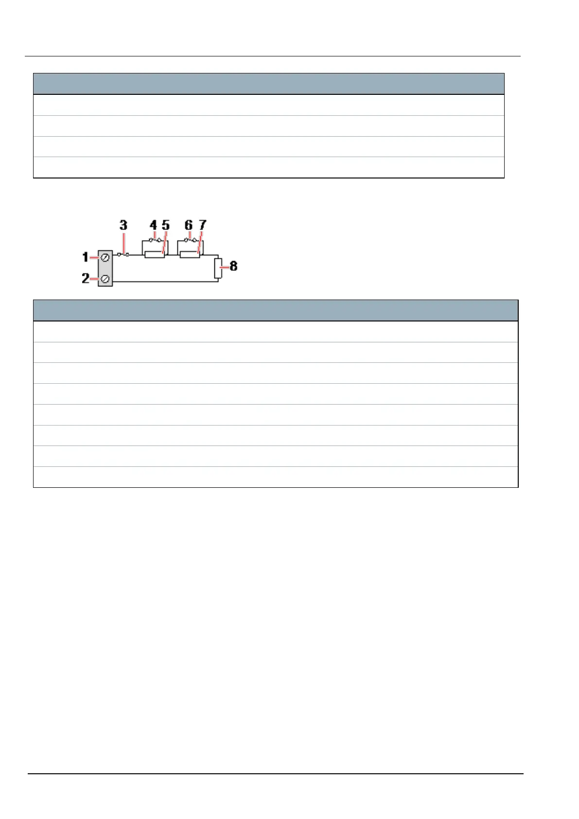
Anti-Masking PIR
The following diagram shows the Anti-Masking PIR configuration:
Number Description
1 Input 2
2 COM
3 Tamper
4 Alarm
5 4k7
6 Detector Fault
7 2K2
8 EOL 4k7
7.1.3.2 Wiring the Outputs
The expander and PSU relay logical outputs can be assigned to any of the SPC system outputs. The relay
outputs can switch a rated voltage of 30V DC at 1A (non-inductive load).
When the relay is activated, the Common terminal connection (COM) is switched from the Normally
Closed (NC) to the Normally open (NO) terminal.
SPC4xxx/5xxx/6xxx – Installation & Configuration Manual Smart PSU
© Vanderbilt 2018 64 A6V10276959-d
11.2018