Do you have a question about the Vanderbilt SPC4 Series and is the answer not in the manual?
Defines the intended audience and their required technical qualifications for using the documentation.
Provides critical safety warnings for installation and operation, including ESD and power source requirements.
Explains warning notices like DANGER and CAUTION, and hazard symbols.
Lists EU directives (EMC, Low Voltage) and compliance standards like EN 55022 and EN 60950-1.
Details SPC compliance with EN50131 standard and lists certifying bodies.
States SPC products tested according to EN 50136 standards.
Outlines software requirements for INCERT approvals, including tamper handling and PIN codes.
Provides criteria for SPC system installation, commissioning, and maintenance to conform to PD 6662:2010.
Details requirements for NF and A2P installation regulations, including housing sealing and HTTP web server disabling.
Provides technical specifications for the SPC4000, including programmable areas, PINs, and event memory.
Details technical specifications for the SPC5000, covering programmable areas, PINs, remote controls, and event memory.
Lists technical specifications for the SPC6000, including programmable areas, PINs, remote controls, and event memory.
Details technical specifications for the SPCP355.300, including on-board zones, relay outputs, and interfaces.
Instructions for mounting the SPC G2 housing, covering opening, internal components, and wall mounting.
Details on mounting the SPC G3 housing, including cover attachment, internal component placement, and wall mounting.
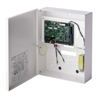
Instructions for mounting the SPC G5 housing, covering opening, internal components, PSU, and expander placement.
Describes components and wiring of the SPCP355.300 Smart PSU, including its expander and backup batteries.
Describes controller hardware for SPC42xx, 43xx, 53xx, 63xx models, including on-board zones and wireless options.
Details controller hardware for SPC5350 and SPC6350 models, including status LEDs and clock reference.
Details the X-BUS interface for connecting expanders to the controller, including configurations and cable types.
Details wiring the 8 on-board zone inputs, including configurations like NEOL, SEOL, DEOL, and Anti-masking PIR.
Covers installing PSTN or GSM modems on the controller board to increase functionality.
Provides recommendations for powering the system from battery only, including charging state and deep discharge protection.
Covers the LCD keypad model, including its interface and data entry capabilities.
Details the Comfort keypad model, including its interface, LEDs, and function keys.
Explains the two programming modes: Full Engineer and Soft Engineer, detailing their functionalities and access.
Describes using the keypad for quick onsite access to system menus and programming, including initial configurations.
Guides through initial system configuration, including language, region, installation type, and security grade.
Explains how to create users, assign panel operations, and manage PINs and user profiles.
Details configuring the keypad with a proximity card/device reader for remote set/unset and programming.
Covers programming wireless fob devices via the keypad, including enrolment, disabling, and clearing alerts.
Explains how to view system faults like OPEN ZONES, ALERTS, ISOLATIONS, and BATTERY status.
Details system options configuration, including SECURITY GRADE, REGION, APPLICATION, and PARTSET settings.
Lists and describes various system timers, including Audible, Confirmation, Dialer Delay, and Setting Authorisation.
Guides on configuring areas, including adding, editing, and setting area types like Standard, ATM, Vault, and Advanced.
Details X-BUS addressing modes (Manual, Auto) and the use of rotary switches for expander identification.
Guides on adding, editing, and deleting users, including setting user ID, name, profile, and PIN.
Covers adding or editing user profiles, including general settings, user/panel rights, and access control.
Covers wireless sensor detection via one-way and two-way modules, including compatible devices.
Guides on configuring zones, including description, zone type, area assignment, and attributes.
Details configuring doors, including description, inputs, group, attributes, timers, and reader information.
Explains how to assign output types to physical ports and expander outputs, covering system and area outputs.
Details configuring serial ports, Ethernet ports, and modems for system communication.
Guides on performing various tests: Bell Test, Walk Test, Zone Monitor, Output Test, Soak Test, and Seismic Test.
Covers system utilities like software version, defaults, backup/restore, system restart, and license management.
Explains manual isolation of zones, system alerts, or X-BUS devices from the keypad to temporarily remove them.
Details viewing recent system events in the EVENT LOG, including date entry for specific events.
Describes viewing zone access events in the ACCESS LOG, allowing selection by door and date.
Explains how to access the ALARM LOG, which displays events like Zones, Alarms, and System Events.
Guides on changing the Engineer PIN, including random PIN generation and PIN digit requirements.
Covers SPC system SMS support for alerts and remote control, including SMS IDs, authentication, and modem configuration.
Details X-10 functionality for controlling peripheral devices via the SPC controller's serial port.
Guides on manually entering and saving the system date and time, used for time-related programming.
Allows engineers to enter system information and contact details, also for keypad pull-down label.
Explains controlling doors, allowing selection of states like NORMAL, MOMENTARY, LOCKED, and UNLOCKED.
Describes setting up SPC Connect ATS for panel registration and remote access via the SPC Connect website.
Explains how to view up-to-date panel information and licensed functionality via the Help menu.
Details accessing the web server on the SPC controller using the Ethernet interface.
Guides on connecting to the panel via USB, including driver installation and Windows XP connection setup.
Instructions for logging into the SPC browser application using user ID, password, and IP address.
Introduces the SPC Home page with System Summary, Alarms, and Video tabs.
Displays status summary of SPC components: system, power, X-BUS, and communications.
Details accessing System Log, Access Log, and Alarm Log for reviewing system events.
Details maximum number of users, profiles, and devices per panel (SPC4xxx, SPC5xxx, SPC6xxx).
Covers wireless sensor detection via one-way and two-way modules, including compatible devices.
Covers configuring controller inputs/outputs, X-BUS connections, system settings, zones, doors, and areas.
Details configuring serial ports, Ethernet ports, modems, FlexC, reporting, and PC tools.
Covers performing operations on panel files: upgrading firmware, managing configuration files, and audio upload.
Introduces SPC Connect PRO and SPC Manager for system management and configuration.
Details establishing remote access via a PSTN telephone line, requiring a PSTN modem and line.
Explains establishing remote access via a GSM network, requiring a GSM module and activated data option.
Details Financial mode operation, suitable for banks/financial businesses, supporting UNSET, PARTSET A/B, and FULL SET.
Describes Commercial mode operation for business installations, supporting UNSET and PARTSET A alarm modes.
Details Domestic mode operation for residential installations, supporting UNSET, PARTSET A/B, and FULL SET alarm modes.
Explains using common areas for setting multiple areas, user access, and keypad assignment scenarios.
Details seismic sensor testing procedures, including manual/automatic test processes and results logging.
Details Blocking Lock operation, requirements, and how it interacts with system setting via Ready to Set signal.
Explains the Authorised Setting functionality for Blocking Locks, requiring a code on an external device.
Describes the mandatory Lock Element for VdS, its function in SET state, and interaction with exit timers and alarms.
Shows two possible connection configurations for PC to SPC controller via Ethernet (hub or direct).
Explains the function of controller status LEDs: Wireless Data, Battery Status, Mains Supply, X-BUS Status, and System Fault.
Guides on calculating the number of expanders/keypads powered from auxiliary terminals based on current draw.
Provides approximations for maximum load current from batteries for stand-by power calculations.
Lists default zone names and types on the controller for Domestic, Commercial, and Financial modes.
Lists SIA codes and their corresponding descriptions for system events.
Lists CID codes and their descriptions for events like MEDICAL, FIRE, PANIC, DURESS, and BURGLARY.
Compares keypad types: Standard, PACE, and Comfort, detailing their functionality, detection, and audio features.
Shows user PIN combinations based on number of digits, variations, and last valid user codes.
Explains duress PIN configuration, including requirements for PIN+1/PIN+2 and consecutive user codes.
Describes automatic zone inhibits in UK/Commercial modes for DD243 functionality, including entry/exit zone behavior.
Covers requirements for mains cable wiring, including disconnect devices, conductor size, and circuit breaker ratings.
Outlines controller servicing, checking event logs for battery tests, and recommended battery replacement.
Details Smart PSU servicing, checking controller event log for battery tests, and replacing PSU fuse/battery.
Describes zone types like ALARM, ENTRY/EXIT, EXIT TERMINATOR, FIRE, FIRE EXIT, LINE, PANIC ALARM, and their processing categories.
Explains zone attributes like Access, Exclude A/B, 24 Hour, Local, Unset Local, Double Knock, and Chime.
Table showing which attributes are applicable to each zone type in the SPC system.
Lists ATS levels for GSM, PSTN, Ethernet, GPRS communication, and attenuation specifications.
Lists supported card readers and card formats for the SPC system, including HD500-EM, iClass, and Wiegand.
Explains SPC E-Bus Gateway for communication with Sintony E-Bus devices, including configuration and addressing.
Defines acronyms used in FlexC communications, including AE, ARC, AS, ATE, ATP, ATS, and RCT.
Lists commands for command profiles, categorized into System, Intruder, User, Calendar, and Communication commands.
Details EN50136-1 ATS Category Timings and FlexC implementation for Ethernet and Modem categories.
Shows settings for Ethernet and Modem ATP categories: event timeouts, polling intervals, and retry intervals.
| Brand | Vanderbilt |
|---|---|
| Model | SPC4 Series |
| Category | Power Supply |
| Language | English |