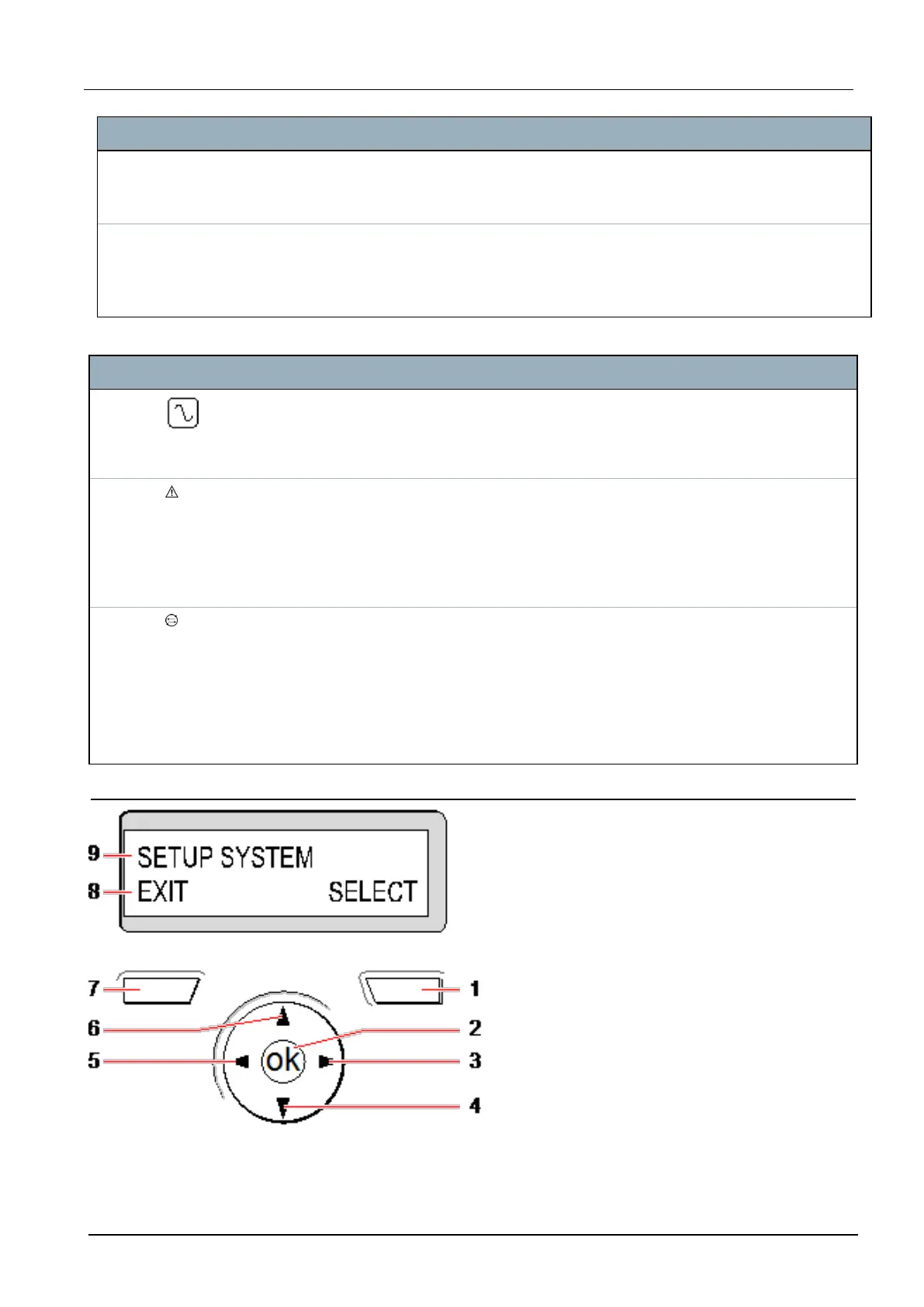
Number Name Description
7 Proximity
device
receiver area
If the keypad has been fitted with a proximity device receiver (see Overview of keypad
types on page375), users should present the Portable ACE Fob to within 1 cm of this
area to SET/UNSET the system.
8 Multi-
functional
navigation
Key
The multi-functional navigation key in combination with the keypad display provides an
interface for programming the system.
LED Status
AC
mains
(Green)
Indicates the presence or failure of the mains supply
FLASHING: AC mains fault detected
STEADY: AC mains OK
System
alert
(Yellow)
Indicates a system alert
FLASHING: System alert detected; display indicates the location and nature of alert. If the
system is SET, then NO indication is given of system alerts
OFF: No alert detected; If a keypad is assigned to more than one area, LED does not indicate an
alert condition if any of those areas is SET
X-BUS
Status
(Red)
Indicates the status of the X-BUS communications when in FULL ENGINEER programming
Flashes regularly: (once every 1.5 seconds approx) indicates communications status is OK
Flashes quickly: (once every 0.25 seconds approx) indicates the keypad is the last expander on
the X-BUS
If the keypad is being installed for the first time and power is supplied to it before a connection to
the controller X-BUS interface is made, the LED remains in the ON state
12.1.2 Using the LCD keypad interface
Keypad display
SPC4xxx/5xxx/6xxx – Installation & Configuration Manual Keypad user interface
© Vanderbilt 2018 95 A6V10276959-d
11.2018