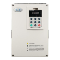
The E5-H High Performance Universal Inverter is a device designed for variable speed operation of three-phase motors. It is not suitable for single-phase motors or applications directly related to human safety, such as medical equipment. The inverter is produced under a strict quality management system, and for applications where failure could cause severe accidents, safety measures like redundancy or bypass should be implemented.
Function Description:
The E5-H Inverter controls the variable speed operation of three-phase motors. It offers both process open-loop control and analog value feedback process closed-loop control. The open-loop control is suitable for most applications, including driving one or multiple motors under the same work conditions. The closed-loop control is for applications requiring general speed control precision, where feedback analog signals can represent parameters like temperature, pressure, and humidity.
Key functions include undervoltage adjustment, switching of AC/DC operation grounding, rotation speed tracing, torque limitation, multi-speed operation (up to 16 speeds), auto-tuning, S-curve acceleration/deceleration, slip compensation, PID regulation, current limiting control, and manual/auto torque increase. It supports various frequency setting modes via the operation panel, UP/DN terminal, analog inputs (AI1 and AI2), or communication with a host computer.
The inverter features a magnetic flux braking function, with options for ongoing action or no action upon deceleration. It also includes a unique multifunctional M key for frequently used operations like JOG, emergent stop, running command mode switch, and menu switching. Multiple menu modes are available: basic, fast, non-factory setting function codes, and last changed 10 function codes. Parameter copying (upload/download) is supported, with an option to forbid overwriting.
Important Technical Specifications:
- Control Mode: Process open-loop control.
- Startup Torque: 180% at 0.50Hz.
- Speed Adjustment Range: 1:100.
- Speed Stabilization Precision: ±0.5%.
- Frequency Range: 0.00 ~ 300.00Hz.
- Startup Frequency: 0.00 ~ 60.00Hz.
- Acceleration/Deceleration Time: 0.1 ~ 36000s.
- Powered Braking Capacity: Braking unit action voltage 650 ~ 750V.
- DC Braking Capacity: Initial frequency 0.00 ~ 300.0Hz; current 0.0 ~ 120.0% (constant torque), 0.0 ~ 90.0% (variable torque); time 0.0 ~ 30.0s.
- Communication Ports: Dual RS485 supporting Modbus protocol (RTU) with a maximum distance of 500m for remote control box.
- Protection Class: IP20.
- Cooling Mode: Natural cooling for lower power classes, forced air convection cooling for higher power classes.
- Efficiency: ≥93% for 7.5kW and below; ≥95% for 45kW and below; ≥98% for 55kW and above.
- Ambient Temperature: −10 ~ +40ºC (derated at 40 ~ 50ºC, output current decreases by 1% per 1ºC rise).
- Humidity: 5 ~ 95%, non-condensing.
- Altitude: 0 ~ 2000m (derated above 1000m, output current decreases by 1% per 100m rise).
- Vibration: 3.5mm, 2~9Hz; 10 m/s², 9~200Hz; 15 m/s², 200~500Hz.
- Storage Temperature: −40 ~ +70ºC.
- Braking Unit: Built-in as standard for products below 15kW; built-in as option or external for 15kW and above.
- DC Reactor: External DC reactor as standard for E5-H-4T90G and above products.
Usage Features:
- Installation: Must be mounted vertically in an electric control cabinet with good ventilation, away from oil mist, metal powder, dust, hazardous gases/liquids, and combustible materials. Maintain specific clearances (e.g., 120mm above, 30mm sides for smaller units; 200mm above, 100mm sides for larger units). Drilling scraps must not fall into the inverter.
- Wiring: Must be performed by qualified electricians. Power supply must be disconnected before wiring. The PE terminal must be reliably grounded. Main circuit terminals should not be touched, and their wires must not contact the inverter enclosure. Braking resistor terminals are specific (⊕2/B1 and B2). Three-phase power supply must not connect to output terminals U/T1, V/T2, W/T3. Output terminals must not connect to capacitors or LC/RC noise filters with phase lead. Power supply phases and rated voltage must match the nameplate. Dielectric strength tests are forbidden. Main and control circuit wires should be laid separately or in a square-crossing mode to prevent interference. Lugs with insulating sleeves are recommended for main circuit wires. Cable sectional area should match inverter power. Output reactors are suggested for motor cables longer than 100m. DC reactor connection is required for inverters equipped with one.
- Operation: Power supply should only be connected after wiring is complete and covers are installed. Do not remove covers in live condition. If auto failure reset or restart is enabled, take isolation measures for mechanical equipment. Terminals are live even when powered on and in stop state. Faults and alarms can only be reset after the running command is cut off. Do not start/stop by switching power on/off. Confirm motor and inverter are within normal use range before operation. Heatsink and braking resistor can be hot; avoid touching. For crane/lifting applications, mechanical contracting brakes are required. Avoid random parameter changes; factory settings often suffice. Interlock contactors for power frequency and variable frequency switching.
- Operation Panel: Available in shuttle type (V6-DP01) for smaller units and button type (V6-DP02) for larger units. Indicators show frequency, current, voltage, speed, percentage, time, multi-function key status, running command mode, and running status (FWD/REV). Keys allow menu navigation, data entry, parameter modification, and inverter control (RUN, STOP/RST, FWD/REV, JOG, emergent stop). Password protection and key locking functions are available.
Maintenance Features:
- Routine Maintenance: Regular checks of temperature, humidity, dust, oil, water, vibration, gas, physical appearance, heatsink fan ventilation, input/output current/voltage, motor overheat, noise, and vibration. Criteria are provided for each item (e.g., temperature −10 ~ +40ºC, no abnormal smell/smoke, physical appearance intact, no fouling in air duct, within allowable operating range).
- Periodic Maintenance: Every three to six months, inspect main circuit terminals, PE terminal, control circuit terminals, internal connections, expansion card connectors, mounting screws, and cleanliness. Perform motor insulation test (500VDC megameter, normal).
- Component Replacement: Cooling fan and electrolytic capacitor are vulnerable. Inspect for bearing wear, blade aging, electrolyte leakage, color change, cracks, shell inflation, and safety valve status. Replace immediately if faults occur.
- Insulation Test: Generally not recommended unless unavoidable. If necessary, use a 500VDC megameter with main power shutdown. Disconnect control board circuits and surge suppressing circuits. Connect main circuit terminals to public conducting wires. Megameter voltage should be applied between the public conducting wire of the main circuit and the PE terminal. Normal indication value is 200MΩ or above.