7
Use the table below to ensure that the ducts you intend to install will be carrying air flows at or under the recommended values.
Avoid installing ducts that will have to carry air flows near the maximum values and never install a duct if its air flow exceeds
the maximum value.
4. INSTALLATION (CONT’D)
4.4 CALCULATING THE DUCT SIZE
VI0003
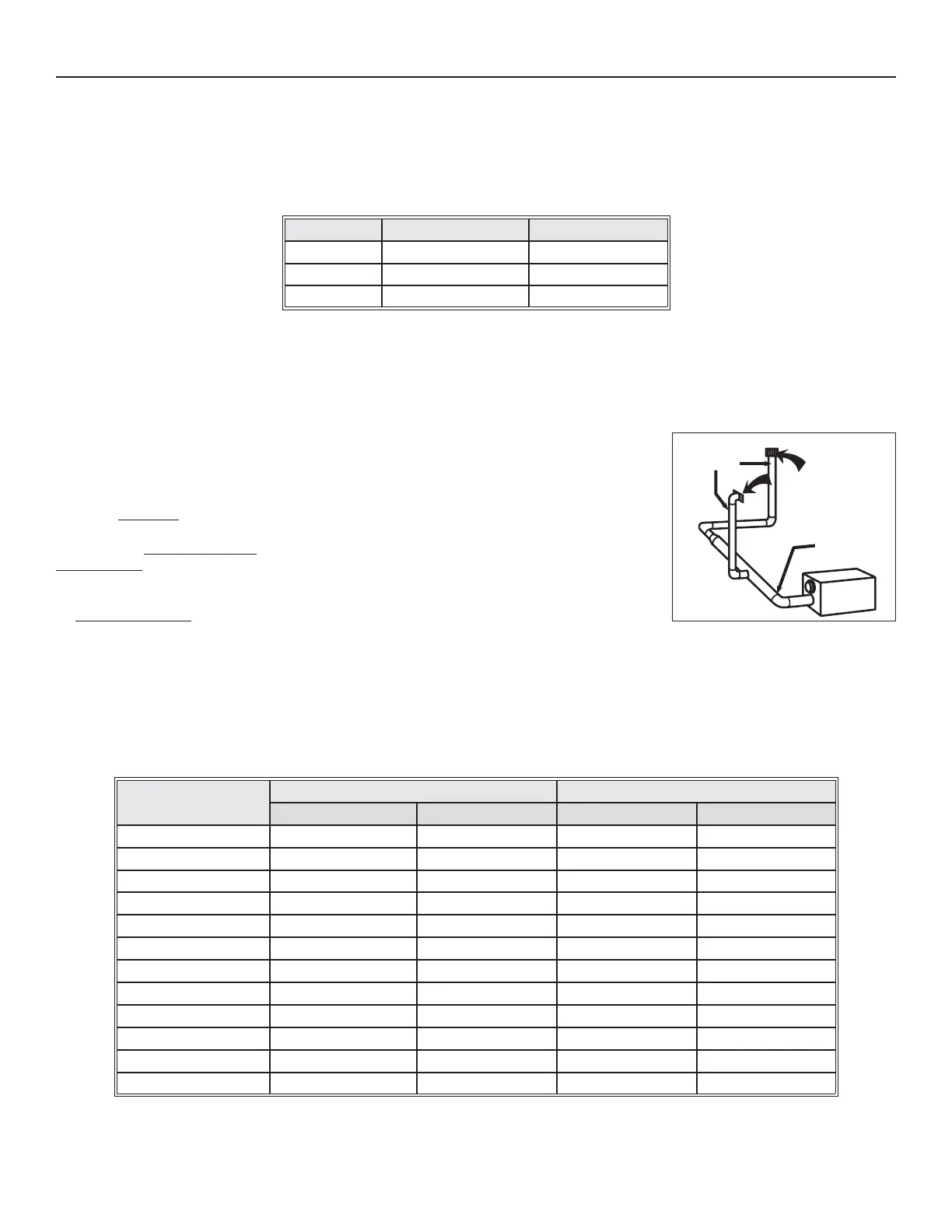
PROBLEM: My installation requires two exhaust registers (both for the bathrooms). I will connect these
registers to a main duct which will connect to the unit (high speed performance value of 110 cfm).
What size of duct should I use for the main exhaust duct and for the two end branches leading to the
registers? (See illustration at right.)
SOLUTION: Main duct: Table above indicates a 6” Ø duct: maximum air flow: 110 cfm. The high speed
air flow of 110 cfm equals the maximum value (110). Therefore a 6” Ø duct or larger is an appropriate
choice for the main exhaust duct.
End branches: Each end branch will have to transport an air flow of 55 cfm (110 divided by 2). Table
above indicates a 5” Ø duct: maximum air flow: 65 cfm. The high speed air flow of 55 cfm is far
enough away from the maximum value (65). Therefore a 5” Ø duct or larger is an appropriate choice
for both end branches.
NOTE: A 4” Ø duct would have been too small because the maximum acceptable value for a 4” Ø
duct is 40 cfm.
4.4.1 EXAMPLE OF CALCULATION
END
BRANCHES
5˝ø
55 CFM
MAIN BRANCH
6˝ø 110 CFM
ROUND DUCT RECTANGULAR DUCT MAXIMUM AIR FLOW
4" 2¼" OR 3¼" X 10" 19 L/S (40 CFM)
5" 2¼"
OR 3¼" X 10" 31 L/S (65 CFM)
6" 3¼"
OR 4" X 10" 52 L/S (110 CFM)
NOTE: Example 4.4.1 uses imperial measures.
The same calculation applies to metric measures.
4.4.2 REGISTERS LOCATION AND AIR FLOWS DISTRIBUTION:
NOVOCLIMAT CHART FOR SIZE OF DUCT CONNECTED TO REGISTER VS. AIR FLOW
The registers location and the air flow distribution must be taken in account when performing ductwork installation. Refer to the Novoclimat
table below to plan the registers location.
REGISTER LOCATION
FRESH AIR FLOWS EXHAUST AIR FLOWS
MINIMUM REQUIRED MAXIMUM ACCEPTABLE MINIMUM REQUIRED MAXIMUM ACCEPTABLE
KITCHEN – –0–
D
INING ROOM 4.7 L/S (10 CFM) 11.8 L/S (25 CFM)– –
L
IVING ROOM 4.7 L/S (10 CFM) 18.9 L/S (40 CFM)– –
O
FFICE 4.7 L/S (10 CFM) 9.4 L/S (20 CFM)– –
R
ECREATION ROOM 4.7 L/S (10 CFM) 18.9 L/S (40 CFM)– –
M
ASTER BEDROOM 9.4 L/S (20 CFM) 9.4 L/S (20 CFM)– –
S
ECONDARY BEDROOM(S) 4.7 L/S (10 CFM) 9.4 L/S (20 CFM)– –
M
AIN BATHROOM – – 23.6 L/S (50 CFM)–
S
ECONDARY BATHROOM(S) – – 14.2 L/S (30 CFM)–
L
AUNDRY ROOM – –0–
W
ORKSHOP – –0–
N
ON-FINISHED BASEMENT 4.7 L/S (10 CFM) 18.9 L/S (40 CFM)– –


 To Next Page