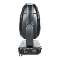
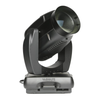
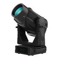
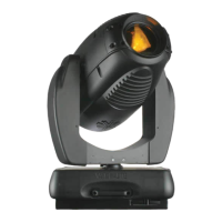
The VL6™ Series Spot Luminaire is a sophisticated lighting device available in three configurations: VL6, VL6B, and VL6C spot luminaires, designed for professional lighting applications.
Function Description:
These luminaires are primarily used to produce variable beam spots with adjustable focus, allowing for soft-edged gobos or spots and smooth gobo crossfades. They feature a full-field dimmer for smooth timed fades and rapid blackouts, and a mechanical iris for continuous beam size control, enabling quick beam size changes and smooth timed beam angle adjustments. The VL6 series also incorporates two 12-position wheels, each with 11 easily loaded positions (plus one open position) for interchangeable dichroic color and gobo selections. Pan and tilt movements are smooth, time-controlled, and continuous, offering 360° pan and 270° tilt. Control is achieved through VARI❋LITE systems or a wide variety of DMX512 consoles. For versatile hanging, each luminaire is equipped with two truss hook brackets.
Important Technical Specifications:
- VL6 Luminaire: Features a 400-watt arc source, a choice of three lenses (narrow, medium, or wide field of view), and a smooth reflector designed to provide either a peaked or flat field.
- VL6B Luminaire: Utilizes a 400-watt arc source, includes rotatable and indexable gobos, and is equipped with a 3:1 zoom optics assembly.
- VL6C Luminaire: Features a more powerful 700-watt arc source, also includes rotatable and indexable gobos, and is equipped with a 3:1 zoom optics assembly.
Usage Features:
The luminaires are designed for dry locations only, and exposure to rain or moisture can cause damage. During operation, exterior surfaces and the lamp become hot, requiring appropriate safety equipment (gloves, eye protection) for handling and adjustment. Arc lamps used in these luminaires emit ultraviolet (UV) radiation, so direct viewing of the lamp should be avoided. Operating the luminaire without a lens or shield is hazardous, and damaged shields, lenses, or UV screens must be replaced. Arc lamps operate under high pressure and at very high temperatures, posing a risk of personal injury or fire from broken lamp particles if the lamp breaks. Arc lamps also require a cool-down period before relighting after a power interruption or severe voltage dip, though automatic relighting may occur depending on the "Lamp Power-Up State" system configuration. The burning position for the lamps is universal.
Maintenance Features:
Maintenance procedures require the luminaire to be disconnected from power. When servicing the lamp, cotton gloves or other coverings should be worn to prevent oil from bare fingers from causing the lamp to explode or burn out prematurely; if touched, the lamp glass must be thoroughly cleaned with denatured alcohol. Lamp alignment for peaked or flat fields is performed using vertical, horizontal, and focus knobs located at the back cap, after allowing the lamp to warm up and setting intensity to 100%.
The manual details replacement procedures for various components, including:
- Lamp Replacement: Involves turning a captive knob at the back cap, sliding the back cap away, removing the old lamp, installing a new one, and re-tightening.
- Color Bulkhead Assembly Replacement: Requires disconnecting MTA receptacles from the yoke termination PCB and removing captive screws to release the bulkhead.
- Standard Gobo or Color Filter Replacement: Filters can be accessed by rotating the wheel after partially sliding out the color bulkhead assembly.
- Dimmer Bulkhead Assembly Replacement: Involves disconnecting MTA receptacles and removing screws securing the assembly.
- Front Assembly Replacement: Requires removing the color bulkhead assembly and disconnecting various MTA receptacles from the yoke termination PCB.
- Lens Assembly Replacement (VL6): Involves removing the front assembly, then removing a hex nut and flat washers from the stepper motor shaft to release the lens assembly. For Wide Field of View (WFOV) lenses, retaining rings must also be removed and discarded, with new ones installed during reassembly. Counterweights may need to be installed or removed depending on the lens type.
- Lens Barrel Assembly Replacement (VL6B/VL6C): Requires removing the front assembly, disconnecting the zoom motor MTA receptacle, and removing a KEPS nut from the edge motor shaft.
- Lens Motor Replacement (VL6): Involves removing the front and lens assemblies, disconnecting motor wires from the yoke termination PCB, and removing screws securing the motor. New MTA connectors must be crimped to motor wires following specific pinouts.
- Edge Motor Assembly Replacement (VL6B/VL6C): Requires removing the front assembly, disconnecting the edge motor MTA receptacle, and removing a KEPS nut from the edge motor shaft. The rotating gobo wheel may need to be rotated to access obscured screws.
- Yoke Termination PCB Assembly Replacement: Involves removing the color bulkhead assembly and disconnecting MTA receptacles and the yoke cable receptacle.
- Ignitor Board Assembly Replacement: Requires removing the dimmer and color bulkhead assemblies, locating the tilt-side yoke leg cover, removing cable ties, disconnecting lamp wires, and removing screws securing the ignitor board.
- Rotating Gobo Wheel Assembly Replacement (VL6B/VL6C): Involves removing the dimmer and color bulkhead assemblies, then removing screws from the rotating gobo wheel assembly.
- Tilt Mechanism Assembly Replacement: Requires removing the tilt-side yoke leg cover, cutting cable ties, disconnecting lamp wires from the terminal strip and ground stud, removing the belt tension and adjustment screw, and disconnecting MTA connectors from the encoder and motor.
- Pan Mechanism Assembly Replacement: Involves removing both yoke leg covers, removing the heatshield, disconnecting input cable wiring from the tilt-side yoke leg and lamp control board, and disconnecting MTA connectors from the encoder and motor.
- Pan/Tilt Belt Tension Adjustment: Loose belts can cause calibration problems; tension should be slowly increased until vibration is dampened, ensuring not to overtighten.
- LCB PCB Assembly Replacement: Requires removing the board-side yoke leg cover and disconnecting all cables before pulling the LCB out from its friction clasps.
- Controller PCB Assembly Replacement: Involves removing the tilt-side yoke leg cover, disconnecting all cables, and removing KEPS nuts securing the PCB.
- Relay Assembly Replacement: Requires removing the tilt-side yoke leg cover and disconnecting all wires before removing screws securing the relay assembly.
Cleaning:
- VL6 NFOV Lens Assembly Dust Prevention and Lens Cleaning: Involves disconnecting the AC input cable, removing the lens assembly, separating lens barrel halves, cleaning lenses and barrel interiors with isopropyl alcohol and lint-free cloth, applying translucent RTV 108 along mating edges, and reassembling.
- VL6B/VL6C Lens Barrel Assembly Dust Protection and Lens Cleaning: Similar to VL6 NFOV, requires removing the lens barrel assembly, separating halves, cleaning, applying Loctite 425 to screws, and reassembling.
- Front Lenses Cleaning: Involves disconnecting power, applying isopropyl alcohol to a lint-free cloth, and gently wiping the lens several times with new cloths.
- Cleaning the Luminaire (Outside): Requires disconnecting power, applying window cleaner sparingly to a lint-free cloth, and wiping the outside surface.
- Cleaning the Luminaire (Inside): Involves disconnecting power, facing the head nose upward, removing the removable cover (and front cover for VL6B/VL6C), and vacuuming the inside of the luminaire head, being careful around PCB components.