Varisco S.p.A.
Z.I. Nord - Terza Strada, 9 - 35129 PADOVA – ITALY
Tel.+39.049.8294111 Email: export@variscospa.com
Fax+39.049.8076762 Web: www.variscospa.com
22
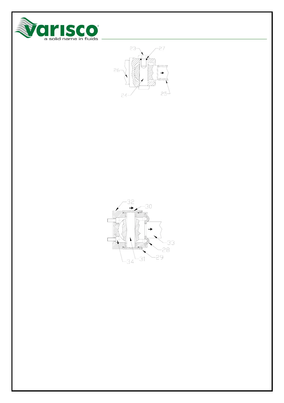
SN7
This kind of joint has no spare parts available. In case of malfunctioning it shall be fully replaced.
9.3.9 JOINT TYPE SN8
1. Remove the internal flat sleeve (28) by operating on the larger part, then move it in the
direction of the black arrow.
2. Remove the grub screw (29).
3. Move the metallic cover backwards (30) in the direction of the arrow. The bushing and the
pin (31) will then be visible.
4. Beat the pin with care, taking care not to damage the bell (32). Then, if necessary, the pin
and the bushes can be replaced.
5. Pull the sphere in the direction of the black arrow. Since it is integral with the propeller shaft
(33), they’ll both be free of the joint. Then the hexagonal-head screws holding the bell to the
rotor (or hollow shaft depending on the joint involved) will be visible
6. Unscrew the screws (34). The bell will be completely free of the rotor (or hollow shaft, as
mentioned above).
SN8
IMPORTANT: Bushes increase the life of the system but are integral with the pin, hence when the
pin is replaced, they shall always be replaced as well.
To re-assemble the internal flat sleeve (28), it is advisable to grease the sphere and use two tools
simultaneously (e.g. two large screwdrivers).
9.3.10 JOINT TYPE SN9
1. Remove the two clamps (35) that hold the sleeve.
2. Force the rubber sleeve backwards (36) in the direction of the black arrow.
3. Remove the grub screw (37).
4. Move backwards the metallic cover (38) in the direction of the arrow. The bushing and the
pin (39) will then be visible.
5. Beat the pin with care, taking care not to damage the bell (40). Then, if necessary, the pin
and the bushes can be replaced.


 To Next Page