Do you have a question about the VARISCO J and is the answer not in the manual?
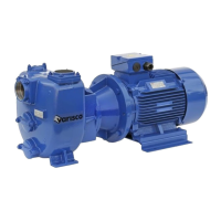
This document describes the Varisco self-priming centrifugal pump, designed for handling liquids containing solids in suspension, and capable of operating with liquids containing air or dissolved gases. These pumps are suitable for liquids with a viscosity up to 50 cSt and are used across various sectors including industry, civil engineering, shipbuilding, waste water treatment, construction, and agriculture. The manufacturer, Varisco Pompe S.r.l., is located in Padova, Italy.
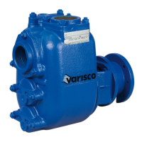
The Varisco self-priming centrifugal pump is designed to efficiently move liquids, even those with suspended solids or dissolved gases. Its self-priming capability eliminates the need for a foot valve in the suction line, as a non-return valve is incorporated into the suction port. The pump's design, featuring an open impeller, allows it to handle challenging fluids effectively.
The pump's nameplate provides crucial technical information, including:
All specified values for capacity, head, power, and speed are based on testing with water at 20°C and a density of 1000 kg/m³.
The pump is guaranteed against defective materials or faulty workmanship for one year from the date of delivery, provided it is used for up to 8 hours per working day. The warranty is void if the pump has been tampered with by third parties. Parts subject to normal wear and tear (seals, diaphragms, gauges, rubber, or plastic items) or damage from misuse are not covered.
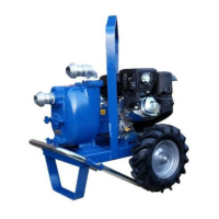
Installation: Pumps supplied on base plates must be anchored to a leveled concrete slab using foundation bolts. The slab must be robust enough to absorb vibrations and maintain alignment. For trailer-mounted pumps, wheels must be blocked with chocks. The pump casing should be suitably supported when coupled to a gearbox for agricultural use.
Pipework: Pipes must be thoroughly cleaned before connection. The suction line diameter should match the pump suction port. Avoid curves, elbows, and constrictions. The pump should be installed as close as possible to the liquid source to minimize suction line length. All suction line connections must be airtight. The delivery line must allow air to escape during priming. Both suction and delivery lines must be mounted to avoid strain on the pump casing. Engine-driven pumps require flexible hoses to isolate pipework from engine vibrations.
Alignment: Before initial operation, the alignment between the pump and motor/engine (coupling) must be checked. While factory-aligned, rechecking during installation is essential. This involves setting the base plate, inserting anchor bolts (without tightening), removing the coupling guard, tightening anchor bolts, and then rechecking alignment. Adjustments are made based on the coupling type (axial, radial, and angular misalignment). The coupling guard must be replaced before starting.
Electrical Connections: Electrical connections must be performed by specialized personnel, following motor and electrical equipment manufacturers' instructions. The motor must be correctly earthed and protected by an adequately rated overload cut-out. For three-phase motors, standard supply is 380V (star connection); for 220V, delta configuration is used. Cable cross-section must match current requirements. After connection, close the delivery line gate valve and check rotation direction (indicated by an arrow on the pump casing). If rotation is incorrect, interchange two supply cable wires. Pumps for brackish water may have galvanic protection (zinc discs) which should be checked and replaced every 1000 hours.
Starting: Before starting, ensure all electrical and mechanical parts are correctly installed and safety devices are operative. Verify the pump rotates in the correct direction.
Mechanical Seal Check:
Filling the Pump Casing: Completely fill the pump casing through the top opening (some models have a plug). The casing does not empty when stopped, so refilling is generally not necessary.
Priming: If the pump does not prime, do not operate it for more than 2 minutes to avoid overheating and seal damage. If priming issues persist, consult the troubleshooting section. Engine-driven pumps should be brought to running speed gradually, and the accelerator limit stop should not be changed to exceed the maximum speed on the nameplate. After priming, check for shaft seal leaks and ensure motor current does not exceed the rated value.
General Maintenance: Before any maintenance, the pump must be stopped, and electrical supply disconnected. Residual liquid may be present, so take precautions if it is hazardous. Periodically check pump operation using system instruments (pressure/vacuum gauges, ammeter). Regular maintenance of wear parts like the impeller and wear plate is recommended.
Replacing the Impeller (03): Drain the pump casing. Remove the casing (52) carefully to avoid damaging the gasket (43). Block the impeller and unscrew the self-locking nut (33). Replace the impeller. If the nut is a dome nut without a nylon self-locking insert, clean the shaft thread and apply LOCTITE 243 before screwing. Reassemble in reverse order, ensuring correct distance between impeller and wear plate.
Replacing the Wear Plate (02): Drain the pump casing. Remove casing (52) and wear plate screws (57). Replace the wear plate (02) and gasket (43) if necessary. Reassemble in reverse, checking impeller-wear plate distance.
Replacing the Check Valve (14): Drain the pump casing. Remove nuts (52.1), suction flange (10), and check valve (14). Install new check valve with hinge towards the top. Clean the valve seat and reassemble. If the check valve has a tongue, bear its weight while tightening nuts.
Replacing Mechanical Seal T, TW, T4W: Drain the pump casing. Remove casing (01), impeller (03), impeller key (60), and head (19). The rotating seal part (40) and shaft sleeve (31) will slide off with the head. Remove stationary seat (39) and gasket (38), and lip seal (41). Clean the head with solvent. Mount new lip seal (smear with oil). Mount stationary seal (39) and gasket (38) (wet with methylated spirits, use a wooden plunger if needed). Reassemble the head carefully, avoiding contact between the shaft and stationary seal seat (especially if ceramic). Tighten head screws (45) and nuts (45.1). Smear rotating seal gasket (40) and shaft sleeve (31) with oil and slip seal onto shaft. Mount seal support ring (25.1) and reassemble impeller (03) and nut (33). If the impeller nut is a dome nut, apply LOCTITE 243. Check impeller-wear plate distance. Reassemble casing gasket (43) (smear with grease) and casing, ensuring impeller rotates freely. Fill seal lubrication chamber.
Replacing TCW, TC8W Cartridge Seals: Drain the pump casing. Remove nuts (52) and casing (43). Remove impeller (03) and nut (33). Disconnect flushing lines. Fix seal lock setting plates (25.4). Loosen shaft sleeve grub screws. Unscrew screws (20.2) fixing seal flange to head. Remove head (19), seal (25), shaft sleeve (31), seal box (20), and gasket (20.1). Replace gasket (20.1) if damaged. Reassemble in reverse. Smear shaft sleeve (31) with oil for assembly. Tighten fixing screws (20.2) carefully. Tighten grub screws. Remove setting plates (25.4). Reconnect flushing lines, begin flushing, and bleed air. The seal must not run dry.
Positioning the Impeller: The distance between impeller blades and wear plate surface should be 0.3-0.6 mm (for 12" models, 0.6-1 mm). This is achieved by using shims (25.2) between the seal support ring (25.1) and the impeller. Further adjustments can be made with casing gaskets (43).
Bearing Maintenance: Bearings are pre-greased and require no maintenance for the first 500 hours. Lubricate appropriately, avoiding excessive grease to prevent overheating.
Replacing Bearings: Empty pump casing. Remove casing, head, mechanical seal, flexible coupling hub, shaft key, and outer bearing cover (08). Extract shaft and bearings using an extractor. Reassemble in reverse.
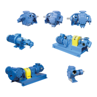
Replacing TWIN-DISC Coupling Blocks (RBD series): Remove pump from its seat. Replace worn blocks. Check aluminum flange. Couple pump to engine. Maximum alignment error is 0.7 mm. Specify shaft diameter and coupling type when ordering.
Replacing SURE-FLEX Coupling Rubber Collar: Unscrew anchor bolts and separate coupling halves. Replace worn rubber collar. Move pump towards motor to fit indentation. Close coupling with 2 mm max. axial play for type J, 3 mm max. for type S. Check radial and angular alignment (using ruler and gauge). Tighten anchor bolts. Specify coupling type and shaft diameter when ordering.
Replacing BALBONI GFB Flexible Coupling Rubber Dowels: Unscrew anchor bolts and separate coupling halves. Replace worn dowels, fixing with adhesive. Move pump towards engine until coupling is closed, then draw back 2-3 mm to separate halves. Tighten anchor bolts. Specify shaft diameter and coupling type when ordering.
Troubleshooting: The manual provides a comprehensive list of operating problems, their causes, and remedies, covering issues like failure to prime, insufficient capacity/pressure, excessive power absorption, vibrations, noise, jamming, short bearing lifetime, and mechanical seal leaks.
Residual Risks: Identified residual risks include knocks, anomalous pressure rises, misuse, and maneuvering errors near the pump.
Repairs: Before repairs, turn off power, close gate valves, allow hot liquids to cool, follow safety procedures for hazardous liquids, empty casing, and clean residues.
Disassembly/Assembly: Instructions are provided for removing the pump from the system and mounting it back, including lifting procedures, reconnecting couplings, checking alignment, and fixing to the base plate.
Spare Parts: To ensure continued operation, it is advisable to acquire spare parts for the first maintenance, including mechanical seal, impeller, wear plate, gaskets, check valve, and self-locking impeller nut. When ordering, specify pump type, serial number, reference number, and part description.
Disposal: Do not abandon in the environment. Metal parts can be recycled. Grease and oil must be recovered and stored as prescribed by legislation. Elastomer gaskets must be removed and disposed of in an approved waste disposal unit.
| Brand | VARISCO |
|---|---|
| Model | J |
| Category | Water Pump |
| Language | English |