6
9.2 Pipework
Clean the pipes thoroughly before connecting them to the pump.
The suction line must have a diameter equal to that of the pump suction port (for diameters greater than that of the pump port, consult
Varisco). If possible, avoid curves, elbows and constrictions which can limit the flow of liquid to the pump. Do not install a foot valve: the
pump has a non return valve (14) incorporated in the suction port (fig. 10).
Install the pump as close as possible to the liquid to be pumped. Try, where possible, to reduce the length of the suction line.
The suction line connections must be completely airtight: check pipe threads, flange gaskets, quick couplings, etc.
The delivery line must let air escape from the system while the pump is priming.
The suction and delivery lines must be mounted in such a way as not to create a strain on the pump casing. Engine driven pumps must
have lengths of flexible hose to isolate the pipework from the vibrations generated by the internal combustion engine
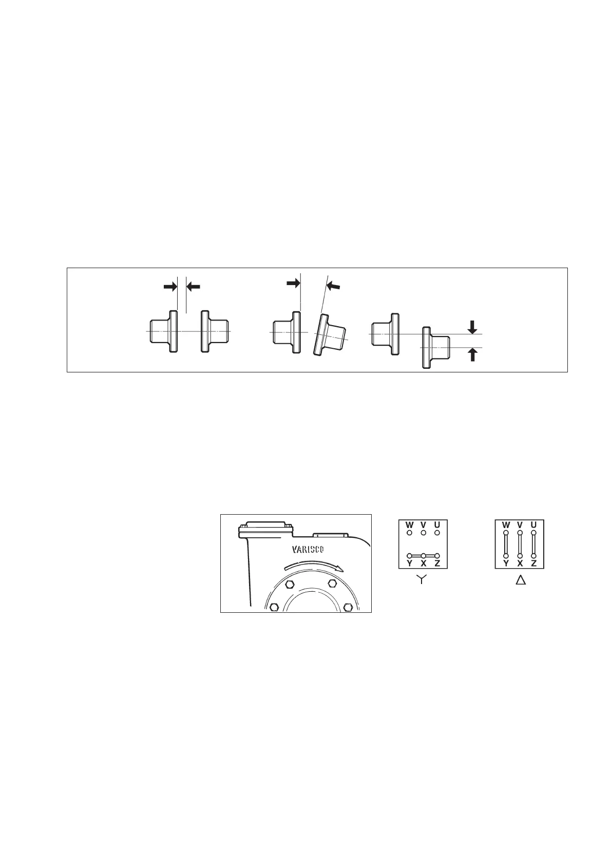
10 ALIGNMENT
Before starting the pump for the first time, it is important to check the alignment between the components of the unit (coupling/
motor).
The alignment of pumps supplied on base plates is checked during manufacture. However, it should be rechecked during installation as
follows:
- set up the base plate on top of the slab and insert the anchor bolts in the holds on the base plate without tightening the nuts completely
- remove the coupling guard.
- tighten the anchor bolt nuts and recheck the alignment as shown in fig.6. Adjust the alignment, if necessary, according to the type of
coupling as described in paragraphs 14.10; 14.11; 14.12.
- replace the coupling guard before starting the pump.
11 ELECTRICAL CONNECTIONS
Electrical connections should only be carried out by specialised personnel.
- Follow the instructions of the manufacturers of the electric motor and electrical equipment.
- Earth the motor correctly and ensure that the electric motor is protected by an adequately rated overload cut-out.
- Three phase electric motors are usually supplied for 380 V (star connection). For 220 V supply, connect the motor terminal box in the delta
configuration as shown in the wiring diagram attached.
- Special voltage motors may be supplied. In this case, follow the instructions supplied with the motor.
- The cross section of the cables must be adequate for the current required by the motor.
- When the motor has been connected, close the delivery line gate valve and check that the direction of rotation is correct.
- The arrow on the pump casing shows the correct direction of rotation (fig.7); if the pump rotates in the opposite direction, interchange two
of the three wires of the supply cable in the terminal box.
On request, pumps for brackish water
can be supplied with galvanic protection
against corrosion. This consists of a
series of zinc discs fixed to the clean
out cover. Check the state of wear of the
zinc every 1000 hours and replace if
necessary.
While the pump is running, check that
the current does not exceed that shown
on the motor name plate.
12 STARTING
Before operating the pump, check that the electrical and mechanical parts of the system have been correctly installed.
Check that all safety devices are operative.
Check that the pump rotates in the correct direction (see paragraph 12).
12.1 Mechanical seal check
Before starting the pump, check the type of mechanical seal shown on the pump name plate.
12.1.1 Pumps with type TW or T4W mechanical seals
Type TW and T4W mechanical seals are filled with grease during assembly. They do not require maintenance during the first 500 hours
of operation of the pump.
12.1.2 Pumps with type T mechanical seals
Type T mechanical seals are not lubricated..
axial
misalignment
radial
misalignment
parallel
misalignment
fig. 6
Star connection Delta connection
fig. 7
 Loading...