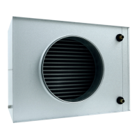
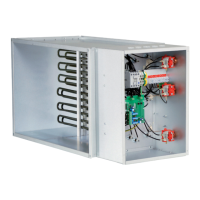
Damper
motor
Exhaust
fan
Alarm
10
EA
GB
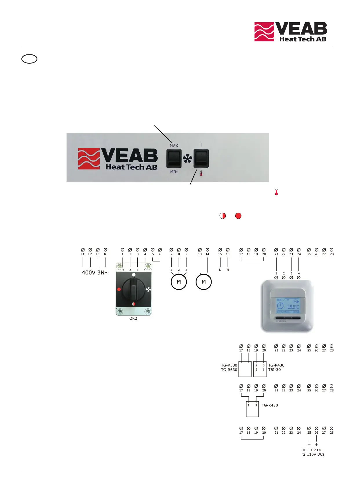
e fan motor function can be changed from continuously running ( | ) to intermittent mode ( ).
Intermittent mode means that the fan motor starts when the thermostat switch on and stops when the
thermostat switch off, if the external function switch, OK2, is in position or .
e link at terminals 5 and 6 is only used in the EA 21 and EA 30 versions. By removing the link,
one contactor (i.e. of the rated power) is disconnected.
INSTALLATION
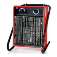
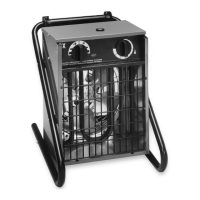
e EA series wall mounted fan heaters comes in five power ranges, i.e. 6kW, 9kW, 14kW, 21kW and 30kW.
e heaters can be tilted 0...15° downwards to direct the airflow. Alternatively/additionally the deflector can
be used to direct the airflow further downwards. e auxiliary deflector EALH 10 / EALH 20 can be used to
direct the airflow horizontally. It is possible to mount the heater in the ceiling with the standard brackets.
e fan motor can be altered from full speed (MAX) to reduced speed (MIN) by using the switch on the front.
Alternative 1
External electronic thermostat, OCC4/OCD4, with adaptive control function.
Terminals #17 and #20 must be linked.
Alternative 2
e heater built-in electronic thermostat is used.
TG-R430 or TBI-30, is used for setpoint value.
TG-R530 or TG-R630, is used as a room sensor.
Alternative 3
e heater built-in electronic thermostat is used.
TG-R430 is used for both the setpoint value and as a room sensor.
Alternative 4
An external excitation voltage 0...10VDC (or 2...10VDC), is used
to control the power. Terminals #17 and #20 must be linked.
e excitation voltage connects to terminals
#25 (negative) and #26 (positive).