EasyManua.ls Logo

Vector TLC-BCR-T - User Manual

Vector TLC-BCR-T
10 pages
To Next Page IconTo Next Page
Loading...
TLC-BCR-T Engineering Manual
Doc: 70-00-0083, Date: 20081219 © 2008 Vector Controls Ltd. Page 1
TLC-BCR-T
Intelligent binary temperature controller
Features
Low power energy consumption: < 1W per unit
Relays switching for outputs each up to 300W
Temperature control for 2 or 4-pipe heating or cooling systems.
Large temperature range from –40°C to 70°C (-40°F to 158°F).
Choose between one 3-point actuator and two binary
heating/cooling stages
Cost saving option with Economy functionality and set point
limitations
External sensor or open contact for remote control, external heat
– cool change or auto-changeover on supply temperature with
selectable activation limits
Control for single stage heating and cooling for 4-pipe systems or
dual stage heating / cooling for 2-pipe systems
Password protected programmable user and control parameters
o Setpoint range limitation
o Access control for setpoints, fan speeds and mode
change
o Access control for heat/cool change and time programs
o Select your display contents
o Selectable behavior after return from power failure
Temperature display in Celsius or Fahrenheit
Deluxe Version:
Clock and time schedule functions
Blue backlight for LCD
Infrared remote controller option:
With special features for Boost and delayed switching on or off
Applications
Air Only Systems:
o Constant Air Volume systems with for single or dual duct systems
Air/Water Systems:
o Radiator control, chilled ceiling, floor heating
Simple individual room control for hotel rooms, meeting rooms, etc.
General Description
The TLC-BCR-T is a stand-alone electronic binary controller with one control loop. The TLC-BCR-T features one internal
and one external NTC temperature sensor input and two binary outputs (Relays).
A detailed parameterization is possible with the use of a simple configuration routine. The TLC-BCR-T can be
configured using the standard operation terminal. No special tools or software is required.
Ordering
Item Name Item code Variant Features
TLC-BCR-T
TLC-BCR-T-W01
40-10 0005
40-10 0005-01
Standard
Cooling only
Binary controller with:
1 TI int or ext
2 DO (Relay) Binary valve control
TLC-BCR-T-D
TLC-BCR-T-D-W01
40-10 0006
40-10 0006-01
Deluxe
Cooling only
Accessories
S-Tn10-2
SD-Tn10-12-2
SD-Tn10-20-2
SDB-Tn10-12
SDB-Tn10-20
SRA-Tn10
SOA-Tn10
40-20 0001
40-20 0002
40-20 0003
40-20 0051
40-20 0004
40-20 0005
40-20 0006
Flying lead sensor with 2 m cable
Flying lead duct sensor 12cm immersion depth, 2m cable
Flying lead duct sensor 20cm immersion depth, 2m cable
Duct sensor with housing, 12cm immersion depth
Duct sensor with housing, 20cm immersion depth
Room sensor
Outdoor sensor
Selection of actuators and sensors
Temperature Sensors: Use only our approved NTC sensors to achieve maximum accuracy. Recommended is SDB-
Tn10-15 as Duct sensor, SRA-Tn10 as Room sensor and SDB-Tn10-15+AMI-10 as immersion sensor.
Binary auxiliary devices: E.g. pumps, fans, on/off valves, etc. Do not directly connect devices that exceed 2(1.2)A.
Observe startup current on inductive loads!
Question and Answer IconNeed help?

Do you have a question about the Vector TLC-BCR-T and is the answer not in the manual?

Vector TLC-BCR-T Specifications

General IconGeneral
BrandVector
ModelTLC-BCR-T
CategoryTemperature Controller
LanguageEnglish

Summary

Applications

Air Only Systems

Constant Air Volume systems with for single or dual duct systems.

Air;Water Systems

Radiator control, chilled ceiling, floor heating.

Ordering

Accessories

List of optional components for the TLC-BCR-T controller.

Mechanical Design and Installation

Installation Procedures

Steps for installing the TLC-BCR-T controller unit and mounting plate.

Mounting Location Guidelines

Guidelines for selecting an appropriate installation site for the controller.

Display and Operation

Power Failure Handling

Behavior of the controller during and after a power interruption.

Frost Protection Mode

How the controller protects against freezing temperatures.

Operation Modes Overview

Description of Comfort, Economy, and Energy Hold Off modes.

Activating Operation Modes

Methods for switching between operation modes.

Clock Operation and Time Schedules (Deluxe Version)

Error Message Reference

Details on error codes (Err1, Err2, FP) displayed by the controller.

Terminal Unit Operation

Unit Control Operations

How to switch the unit ON, OFF, and toggle between modes.

Display and Setpoint Adjustment

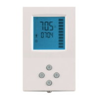
Understanding the display and changing temperature setpoints.

Accessing Advanced Settings

Navigating the advanced setup menu for configuration.

Clock and Time Schedule Setup

Configuring time settings and programmable schedules (Deluxe only).

Setting User Parameters

Accessing Parameter Settings

Procedure to access user and expert parameter settings.

User Parameters Reference

Overview of available user parameters and their settings.

Control Functions

Setpoint Configuration

Defining minimum and maximum limits for setpoints.

Control Sequence Logic

Details on 4-pipe/2-pipe operation, hysteresis, and delays.

Output Configuration Options

Selecting between 3-point or binary output control.

Binary Control Modes

Configuration for binary outputs and reversing valves.

Advanced Control Features

Remote Enable Functionality

Using external inputs for remote ON/OFF control.

Occupation Sensor Integration

Controlling modes via occupation sensors or key cards.

Heat;Cool Changeover Methods

Automatic switching based on media or outside temperature.

Configuration Parameters

Firmware Version Identification

How to identify the controller's firmware version.

Control Parameter Reference

Detailed listing and explanation of control parameters.

Related product manuals