1. INTRODUCTION
Your new Vector MAXX SST™ 175 inverter is one in a series of the most
advanced DC to AC inverters available today. With proper care and
appropriate usage, it will give you years of dependable service in your car,
truck, RV or boat.
The inverter supplies 175 watts of continuous power, with a 350 watt peak,
in the form of one household-type receptacle that is ready to deliver
110/120V AC power whenever and wherever you need it! The heavy-duty
inverter has enough power to run almost any household or electronic
appliance, including color TVs (up to 20"), TV/VCR combinations, laptop
computers, camcorders, cellular phones, camcorders, power tool chargers,
lamps and many more. Added safety features include automatic shutdown
and a low battery alarm to prevent damage to your battery.
This power inverter is configured with the latest soft start technology (SST™)
to improve inverter operation. Before introduction of soft-start, high start-up
currents from large inductive loads could shut down the inverter. Three
major features are incorporated in SST™. First, gradual voltage ramp-up
during inver ter start-up. This eliminates failed cold starts under load .
Second, output that momentarily dips in voltage and quickly recovers to allow
large mot orized loads to start. This eliminates most shutdowns from momentary
overloads. Last, the inverter automatically re-start s when an overload that
caused inverter shutdown is removed. Previously , manual reset was required.
2. CONTROLS, INDICATORS AND CONNECTORS
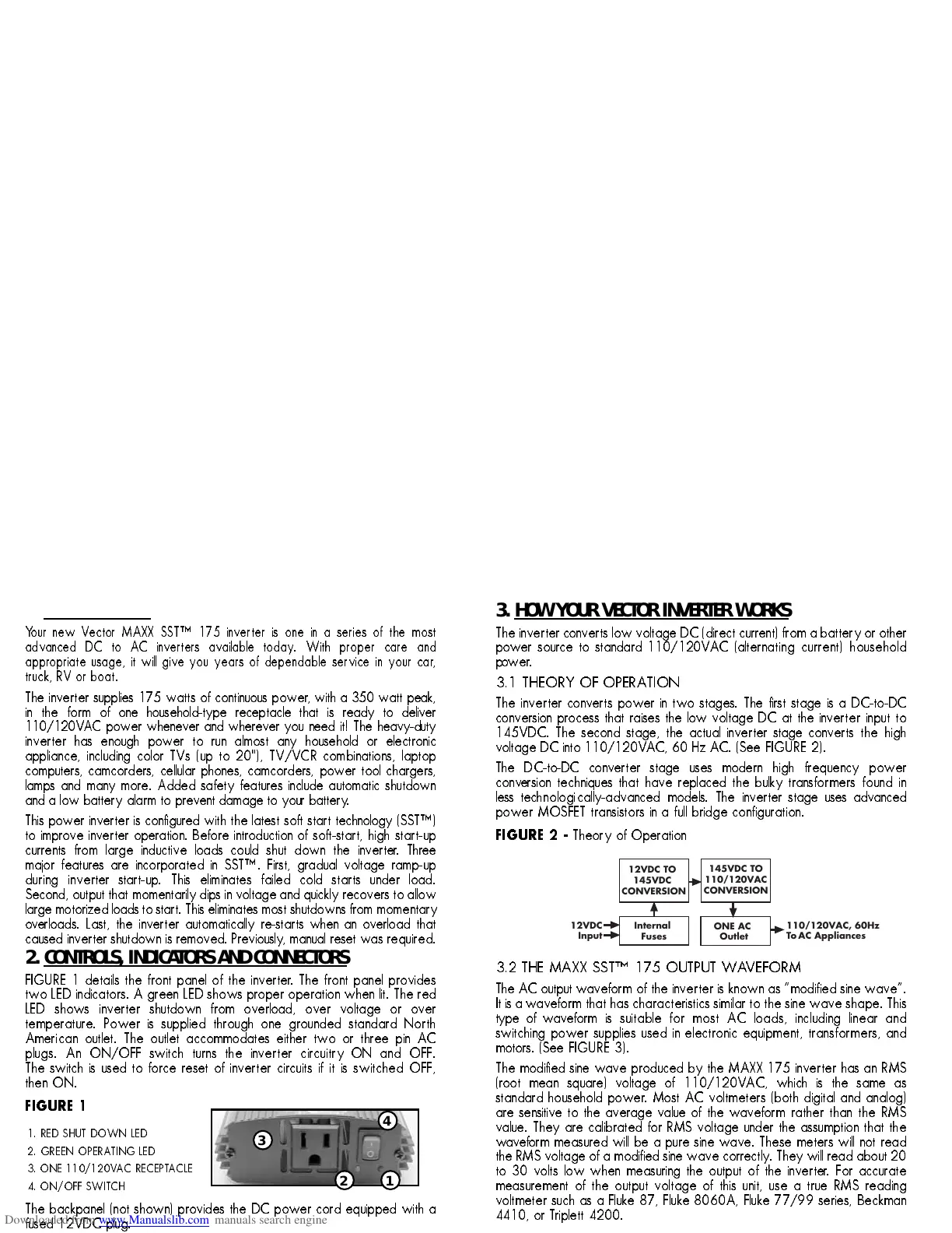
FIGURE 1 details the front panel of the invert er. The front panel provides
two LED indicators. A green LED shows proper operation when lit. The red
LED shows inverter shutdown from overload, over voltage or over
temperature. Power is supplied through one grounded standard North
American outlet. The outlet accommodates either two or three pin AC
plugs. An ON/OFF switch turns the inverter circuitry ON and OFF.
The switch is used to force reset of inverter circuits if it is switched OFF,
then ON.
FIGURE 1
The backpanel (not shown) provides the DC power cord equipped with a
fused 12VDC plug.
1. RED SHUT DOWN LED
2. GREEN OPERA TING LED
3. ONE 110/120V AC RECEPT A CLE
4. ON/OFF SWITCH
3. HOW YOUR VECTOR INVERTER WORKS
The inverte r converts low voltage DC (direct current) from a battery or other
power source to standard 110/120V AC (alternating current) household
power.
3.1 THEORY OF OPERA TION
The inverte r converts power in two stages. The first stage is a DC-to-DC
conversion process that raises the low voltage DC at the inverter input to
145VDC. The second stage, the actual inverter stage converts the high
voltage DC into 110/120V AC, 60 Hz AC. (See FIGURE 2).
The DC-to-DC converter stage uses modern high frequency power
conv ersion techniques that have replaced the bulky transformers found in
less technologically-advanced models. The inverter stage uses advanced
power MOSFET transistors in a full bridge configuration.
FIGURE 2 -
Theory of Operation
3.2 THE MAXX SST™ 175 OUTPUT WAVEFORM
The AC output waveform of the inverter is known as “modified sine wave”.
It is a waveform that has characteristics similar to the sine wave shape. This
type of waveform is suitable for most AC loads, including linear and
switching power supplies used in electronic equipment, transformers, and
motors. (See FIGURE 3).
The modified sine wave produced by the MAXX 175 inverter has an RMS
(root mean square) voltage of 110/120VAC, which is the same as
standard household power. Most AC voltmeters (both digital and analog)
are sensitive to the average value of the waveform rather than the RMS
value. They are calibrated for RMS voltage under the assumption that the
waveform measured will be a pure sine wave. These meters will not read
the RMS voltage of a modified sine wave correctly. They will read about 20
to 30 volts low when measuring the output of the inverte r. For accurate
measurement of the output voltage of this unit, use a true RMS reading
voltmeter such as a Fluke 87, Fluke 8060A, Fluke 77/99 series, Beckman
4410, or T riplett 4200.