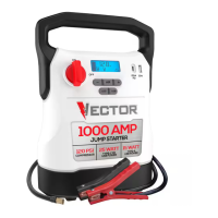
7
and”–” signs. The Alarm Icon and the Jump Starter Icon will flash. The
backlit LCD Screen will display the following:
Turn off the Jump Starter Power Switch; connect the clamps to the
battery, making sure the clamps are connected with correct polarity; then
turn the Jump Starter Power Switch back on.
• Always disconnect the negative (black) jumper cable first, followed by the
positive (red) jumper cable, except for positive grounded systems.
Procedure
Take the following steps, observing all cautions and warnings in the
“Important Safety Instructions” section at the front of this manual.
1. Turn off vehicle ignition and all accessories (radio, A/C, lights,
connected cell phone chargers, etc.). Place vehicle in “park” and set
the emergency brake.
2. Make sure the Jump Starter Power Switch is in the OFF position.
3. Remove jumper clamps from clamp tabs. Connect the Red Clamp first,
then the Black Clamp.
4. Procedure for jump-starting a NEGATIVE GROUNDED SYSTEM
(negative battery terminal is connected to chassis) (MOST COMMON)
4a. Connect Positive (+) Red Camp to vehicle battery’s positive
terminal.
4b. Connect Negative (–) Black Clamp to chassis or a solid, non-
moving, metal vehicle component or body part. Never clamp
directly to negative battery terminal or moving part. Refer to the
automobile owner’s manual.
5. Procedure for jump-starting POSITIVE GROUND SYSTEMS
Note:
In the rare event that the vehicle to be started has a Positive Grounded
System (positive battery terminal is connected to chassis), replace steps
4a and 4b above with steps 5a and 5b, then proceed to step 6.
5a. Connect Negative (–) Black Clamp to vehicle battery’s negative
terminal.
5b. Connect Positive (+) Red Clamp to vehicle chassis or a solid,
non-moving, metal vehicle component or body part. Never clamp
directly to positive battery terminal or moving part. Refer to the
automobile owner’s manual.
6. When the clamps are connected properly, the backlit LCD Screen will
display the following to indicate the unit is ready to jump-start:
The Battery Status Icon, Battery Voltage Indicator, Clamp Icons and the
“+” and”–” signs light solid. The Jump Starter Icon will flash to indicate
the clamps are properly connected.
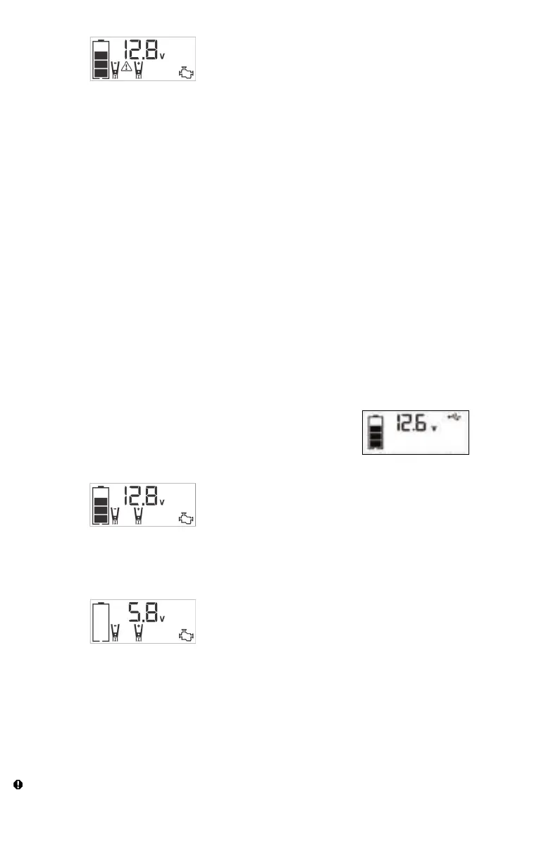
7. Turn the Jump Starter Power Switch to ON. Turn on the ignition and
crank the engine in 5-6 second bursts until engine starts. The backlit
LCD Screen will display the following:
The Battery Status Icon, the Battery Voltage Indicator, Clamp Icons and
the “+” and”–” signs light solid to indicate the unit is jump-starting. The
Jump Starter Icon flashes. The Jump Starter Icon lights solid if vehicle
is started.
8. Turn the Jump Starter Power Switch to OFF.
9. Disconnect the Negative (–) Engine or Chassis Clamp first, then
disconnect the Positive (+) Battery Clamp.
Note: If the unit is malfunctioning after jump start procedure, please
recharge the unit with the supplied AC charger to reset the unit.
IMPORTANT: Always turn the unit off when not in use. Recharge this unit fully
after each use.
CAUTION – To reduce the risk of property damage:
• Vehicles that have on-board computerized systems may be damaged if
vehicle battery is jump-started. Before jump-starting this type of vehicle,
read the vehicle manual to confirm that external-starting assistance is
advised.
• Excessive engine cranking can damage the vehicle’s starter motor. If
the engine fails to start after the recommended number of attempts,
discontinue jump-start procedure and look for other problems that need
to be corrected.
• If vehicle fails to start, turn off the ignition, turn off the Jump Starter Power
Switch, disconnect the jump-start system’s leads and contact a qualified
technician to investigate why the engine did not start.
LED AREA LIGHT
The built-in LED Area Light is controlled by the Area Light Power Button on
the control panel (refer to the Features section to locate). Press the Area
Light Power Button once to turn the light on. Press the Area Light Power
Button again to turn the Area Light off.
IMPORTANT: When the Area Light Power Button is pressed to turn it on, a
beep will sound. The backlit LCD Screen will turn on for 10 seconds (only)
and will then continuously display the Battery Status Icon and Battery
Voltage Indicator.
Periodically check the unit’s Battery Status on the backlit LCD Screen.
Four solid bars in the Battery Icon indicates a full battery. When the battery
level is nearly empty with only one solid bar or empty Battery Status Icon,
the unit must be recharged at this time or the unit’s built-in low voltage
protection will activate. The unit will automatic shut down after a short
period.
Make sure the Area Light is turned off when the unit is being recharged
or stored.
USB CHARGING PORTS
The USB Power Button and the two USB Ports are located on the front
of unit.
1. Press the USB Power Button to turn the USB Ports on. A beep
will sound and the backlit LCD Screen will continuously display the
following:
The Battery Status Icon and Battery Voltage Indicator will light solid, as
well as the USB Icon, indicating the USB ports are ready to use.
2. Plug the USB-powered device(s) into the USB Power Port(s) and
operate normally.
Press the USB Power Button again to turn off the USB Ports. Make sure
the USB Ports are turned off when the unit is being recharged or stored.
IMPORTANT NOTES:
The USB-A Port provides up to 15W output power. The USB-C Port
provides up to PD 25W output power. The total output is up to 5V/15W
when the USB-C and USB-A used simultaneously.
When the USB Ports are in use, the unit will monitor for the following USB
fault conditions on the USB Ports: low battery voltage fault, overload and
short circuit.
If a low internal battery voltage fault condition exists, the Digital Display
will show the Battery Voltage Indicator, the EMPTY Battery Status Icon
and Fault Icon on the LCD Screen will flash for 10 seconds before the unit
automatic shut down.
If overload or short circuit fault condition exists, the USB Ports will shut
down automatically.
Should this occur:
• Disconnect the USB-powered device and press the USB Power Button
again to turn it off immediately.
• Make sure the unit does not need to be recharged.
• Allow the unit to cool down for several minutes before attempting to use
the USB Ports again.
• If a fault occurs again, make sure that the total draw of the USB devices
plugged into the USB ports do not exceed the maximum rating.
• If individual USB device is within specifications and the fault occurs, have
the USB device checked for malfunction and do not continue to use it
with the USB Ports.
 Loading...