EasyManua.ls Logo

Vectronics VC-300M User Manual

Default Icon
8 pages
To Next Page IconTo Next Page
Page #1 background imageLoading...
Page #1 background image
VC-300M Antenna Tuner Owner's Manual
1
Vectronics VC-300M Antenna Tuner
FEATURES
The Vectronics VC-300M Antenna Tuner optimizes the performance of your antenna and
transmitter, receiver, or transceiver by providing adjustable impedance matching. The
VC-300M also measures the Power and Standing Wave Ratio (SWR), allowing you to
adjust for the lowest possible ratio for the selected transmit frequency. The VC-300M
utilizes a precision frequency compensated lighted dual movement SWR/Power meter
which can show either peak or average readings.
SPECIFICATIONS
FRONT PANEL INDICATORS
Meter ....................................Dual movement lighted cross needle Power and SWR meter.
FRONT PANEL CONTROLS
TRANSMITTER Tuning .....Continuous rotation capacitor
ANTENNA Tuning..............Continuous rotation capacitor
INDUCTANCE....................48 Turn Switched Rotary Inductor
RANGE................................2 position switch: 30W/300W
METER ................................2 position switch: PEAK/AVG
LAMP...................................2 position switch: ON/OFF
REAR PANEL CONNECTORS
INPUT ..................................SO-239 Connector
OUTPUT..............................SO-239 Connector
12 V AC/DC.........................2.5 mm Barrel Connector
GROUND.............................Post/Wingnut
OTHER
Frequency Coverage.............1.8-30 MHz
Power....................................150 Watts Continuous; 300 Watts pep, SSB
Dimensions...........................3.6" (92 mm) H x 7.25" (184 mm) W x 8.75" (222 mm) D.
Weight..................................2.5 lbs. (1.15 kg)
Question and Answer IconNeed help?

Do you have a question about the Vectronics VC-300M and is the answer not in the manual?

Vectronics VC-300M Specifications

General IconGeneral
BrandVectronics
ModelVC-300M
CategoryTuner
LanguageEnglish

Summary

Product Features

Technical Specifications

Front Panel Indicators

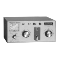
Details the dual movement lighted cross needle SWR/Power meter.

Front Panel Controls

Lists transmitter tuning, antenna tuning, inductance, range, meter, and lamp controls.

Rear Panel Connectors

Specifies SO-239, barrel connector, and post/wingnut connectors on the rear.

Other Specifications

Covers frequency coverage, power handling, dimensions, and weight.

Front Panel Functions

Transmitter Control

Describes the continuously adjustable input capacitor.

Power / SWR Meter

Explains the dual needle meter for forward and reflected power and SWR measurement.

Antenna Control

Details the continuously adjustable output capacitor.

Inductor Control

Refers to the 48-position rotary switch for varying inductance.

Range Switch

Explains the two-position switch for power meter range settings.

Lamp Switch

Describes the two-position push button for turning the lamp on or off.

Rear Panel Connectors

Transmitter In Connector

Coaxial connector for input from SWL receiver or transmitter.

Antenna Connector

Coaxial connector for output.

12V AC/DC Connector

Barrel connector for meter lamp power.

Ground Connector

Post/Wing-nut type ground connector.

Installation

Installation Procedures

Connect Coaxial Cable

Connect transmitter/receiver to the rear panel transmitter connector.

Pre-Tuning Safety

Set controls as outlined before applying transmitter power to avoid damage.

Initial Tuning Power Setting

Begin tuning with transmitter at a low output setting (10 to 20W).

Tuning Process

Band and Frequency Selection

Select the desired band and frequency of operation.

Initial Control Settings

Set Transmitter, Antenna, and Inductor controls to suggested settings.

Low Power Transmission

Set transmitter to a low power output or tune position.

Tuning Adjustments and Notes

Power Level Adjustment

Adjust controls for maximum noise/signal and minimum reflected power at 40-50W.

SWR Reading and Optimization

Read SWR on red scale and repeat adjustments for lowest SWR (2:1 or lower).

Recommended Tuning Notes

Provides notes on SWR targets, antenna adjustments, and re-tuning.

Meter Calibration

Calibration Procedure Steps

Step-by-step guide to calibrate the SWR/Power meter using RF power.

Schematic Diagram

Technical Assistance

Related product manuals