EasyManua.ls Logo

Vectronics VC-300DLP User Manual

Vectronics VC-300DLP
9 pages
To Next Page IconTo Next Page
Page #1 background imageLoading...
Page #1 background image
VC-300DLP Antenna Tuner Owner's Manual
1
VECTRONICS
VC-300DLP Antenna Tuner
FEATURES
The Vectronics VC-300DLP Antenna Tuner optimizes the performance of your antenna and
transmitter, receiver, or transceiver by providing adjustable impedance matching. The VC-
300DLP also measures the Power and Standing Wave Ratio (SWR), allowing you to adjust for
the lowest possible ratio for the selected transmit frequency. The VC-300DLP utilizes a
precision frequency compensated lighted dual movement SWR / power meter which can show
either peak or average readings. Also included is a built-in Dummy Load for tuning purposes
which is easily switched in and out of the circuit.
SPECIFICATIONS
FRONT PANEL INDICATORS
Meter ..................................... Dual movement lighted cross needle Power and SWR meter.
FRONT PANEL CONTROLS
TRANSMITTER................... Continuous rotation capacitor.
ANTENNA............................ Continuous rotation capacitor.
INDUCTANCE..................... 48 Turn Switched Rotary Inductor.
OUTPUT SELECT ............... Eight position: DIRECT Coax 1, Coax 2, Bypass, and Dummy
Load; TUNED Coax 1, Coax 2, Wire, and Dummy Load.
RANGE ................................ 2 position switch: 30W / 300W
METER .................................2 position switch: PEAK/AVG
LAMP.................................... 2 position switch: ON / OFF
REAR PANEL CONNECTORS
COAX 1................................. SO-239 Connector
COAX 2................................. SO-239 Connector
BYPASS................................ SO-239 Connector
TRANSMITTER IN..............SO-239 Connector
BALANCED LINE ...............Dual Banana Jack
WIRE.....................................Banana Jack
Question and Answer IconNeed help?

Do you have a question about the Vectronics VC-300DLP and is the answer not in the manual?

Vectronics VC-300DLP Specifications

General IconGeneral
Frequency Range1.8-30 MHz
Impedance50 ohms
Antenna SwitchYes
Power300 Watts PEP
MeterSWR/Wattmeter

Summary

FEATURES

SPECIFICATIONS

FRONT PANEL INDICATORS

Dual movement lighted cross needle Power and SWR meter.

FRONT PANEL CONTROLS

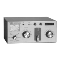
Lists Transmitter, Antenna, Inductor, Output Select, Range, Meter, Lamp controls.

REAR PANEL CONNECTORS

Lists rear panel connectors: COAX 1/2, BYPASS, TRANSMITTER IN, BALANCED LINE, WIRE.

OTHER

CONTROLS / CONNECTORS

FRONT PANEL FUNCTIONS

Explains the operation of the Transmitter, Power/SWR Meter, Antenna, and Output Select controls.

REAR PANEL CONNECTORS

Details the function of each rear panel connector, including COAX, BYPASS, and BALANCED LINE.

INDUCTOR

RANGE

METER

LAMP

REAR PANEL CONNECTORS

TRANSMITTER IN

Coaxial connector for input from SWL receiver or transmitter.

COAX 1

Coaxial connector for output to Antenna One.

COAX 2

Coaxial connector for output to Antenna Two.

BYPASS

Coaxial connector for third coax output. Bypasses tuner, but meter circuits remain active.

GROUND

Post / Wing-nut type ground connector.

BALANCE OUTPUT

Banana jack connectors for output to RF balanced twin lead antennas.

END FED WIRE

Banana jack for output to a single-wire antenna.

12V DC

Barrel connector for meter lamp power.

INSTALLATION

WARNING: HIGH RF VOLTAGES

Warning about high RF voltages at banana connectors during transmission.

INSTALLATION PROCEDURES

Step-by-step guide for connecting transmitter, antennas, and feedlines.

TUNING

WARNING: DO NOT OPERATE WITH COVER OFF

Warning against operating with the cover off or changing inductor switch with high power.

TUNING PROCEDURE

Steps for selecting bands, setting controls, and adjusting for lowest SWR.

WARNING: DO NOT EXCEED 150 WATTS

Caution to not exceed 150 watts if SWR is greater than 4:1.

NOTES

ACCEPTABLE SWR LEVELS

Guidelines on acceptable SWR ratios (1:1 to 2:1).

ANTENNA ADJUSTMENT

Tips for improving SWR by adjusting antenna or feedlines.

SELECTING BEST SETTING

Criteria for choosing best tuning setting: high forward power, low reflected power, high capacitance.

RETUNING NECESSITY

Procedure must be repeated when connecting a new or different antenna.

TECHNICAL ASSISTANCE

CONTACT INFORMATION

Provides phone, mail, and fax details for technical support.

METER CALIBRATION

METER CALIBRATION PROCEDURE

Step-by-step instructions for calibrating the Forward and Reflected power meters.

SCHEMATIC DIAGRAM

Related product manuals