VC-300DLP Antenna Tuner Owner's Manual
8
METER CALIBRATION
METER CALIBRATION PROCEDURE
•
Connect transceiver to TRANSMITTER IN connector.
•
Connect external 50
Ω
load to COAX 2 connector.
•
Set the OUTPUT SELECT switch to the COAX 2 DIRECT position.
•
Set the RANGE button to 300 W and the PEAK/AVG button to AVG.
•
Apply 100 W of RF at 14.0 MHz.
•
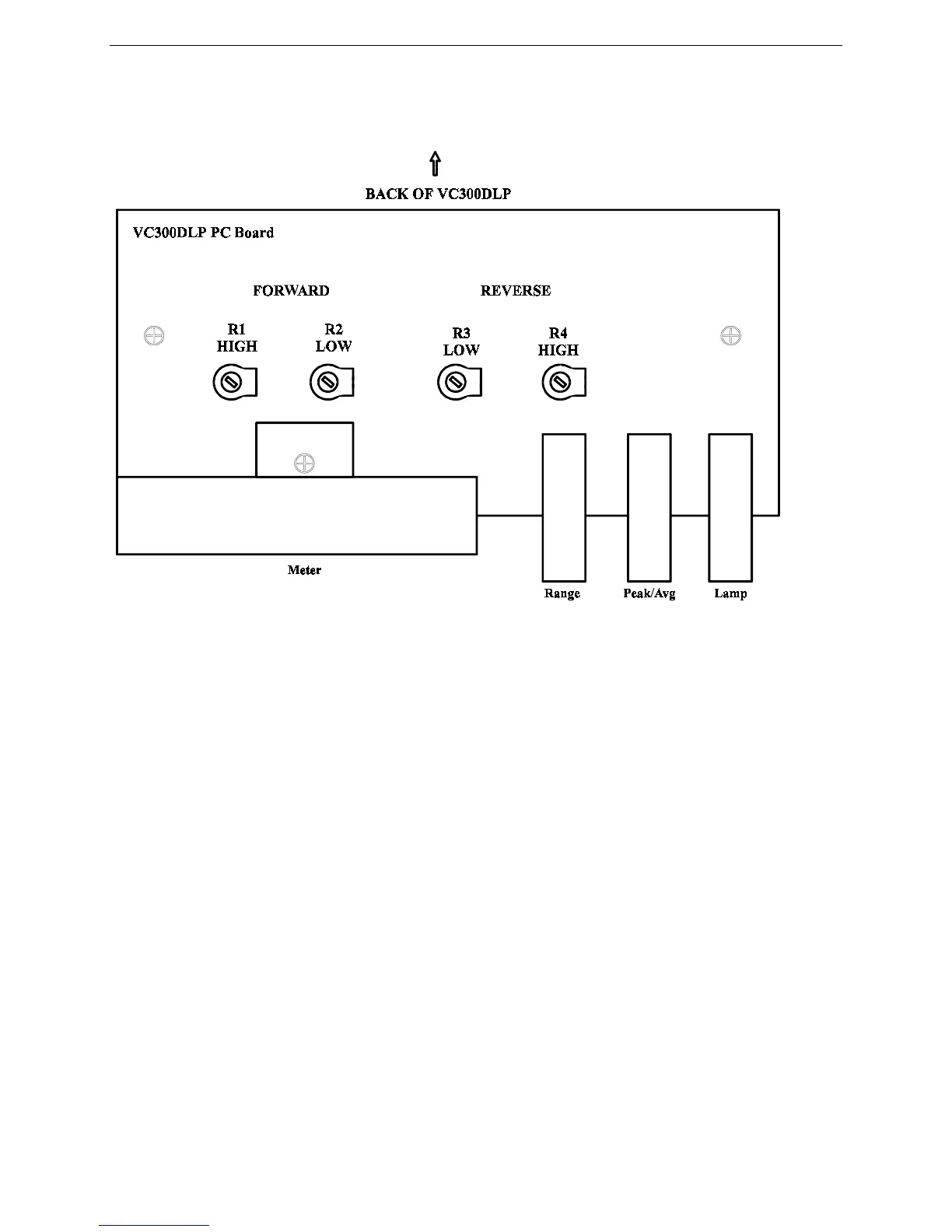
Adjust R1 (see Figure 1) so that 100 W of FORWARD power is read on the meter.
•
Reduce the RF power to 10 W and set the RANGE to10 W.
•
Adjust R2 so that 10 W of FORWARD power is read on the meter.
•
Reverse the transceiver and load connectors on the rear panel.
•
Set the RANGE to 300 W.
•
Apply 10 W of RF power and adjust R4 to read 10 W of REFLECTED power.
•
Set the RANGE to30 W.
•
Apply 2W of RF power and adjust R3 to read 2 W of REFLECTED power.