VPS Installation Tools Required
6
An desiccant tube is recommended for the VPS in wired/wireless vent stack installations (see kit in Table 3).
Tools Required
1. Wrenches suitable for tightening tubing/pipe fittings.
2. Necessary pipe fitter’s equipment (including threading equipment as needed) and a non-hazardous work
space suitable to modify the dispenser vapor line or the vapor vent stack for VPS sensor installation.
3. T25 Torx bit for tamper-resistant screws to secure vent stack enclosure door.
Under Dispenser Installation Steps
1. Before installing this device, turn Off, tag/lock out power to the system, including console and submersible
pumps.
2. Determine which dispenser is closest to the tank/tanks being monitored. Remove that dispenser’s lower
sheet metal doors to gain access to the vapor plumbing.
3. Refer to VPS dispenser installation examples in Figure 1 through Figure 5 to locate a suitable port or plumb a
suitable fitting for the VPS tubing in either the vapor return shear valve or in the vapor return line.
4. Install one of the 68CA-4-4 male connectors (item 2 in Table 1) from the kit into the tapped hole.
5. Install VPS (item 1 in Table 1) vertically to the dispenser frame or piping using the 2-inch conduit clamp,
rubber shim, and necessary bolts, nuts, and washers from the included Universal Sensor Mounting kit. Wrap
the rubber shim (item 10 in Table 1) around the sensor before inserting it into the clamp.
The VPS sensor must be installed in a VERTICAL position with the sensing port pointing
down. Its connection in the base of the dispenser in the vapor return line must be made
BE
LOW the vapor return line shear valve mechanism, AND BELOW the Air Flow Meter (AFM)
outlet (if an AFM is installed).
6. Attach one end of the 62CA-4 union (item 3 in Table 1) to the pressure sensing port in the base of the VPS.
7. Install the remaining 68CA-4-4 male connectors (item 2 in Table 1) from the kit into each of the three ports in
the 3-way calibration valve (item 13 in Table 1).
8. Measure, fabricate, and install a ¼" OD copper tube (item 12 in Table 1) that runs between the 62CA-4
union in the base of the VPS and the center port of the 3-way calibration valve.
9. Measure, fabricate, and install a ¼" OD copper tube that runs between the ¼" tube end of the male
connector fitting installed beneath the shear valve mechanism and the right port on the 3-way valve, being
careful not to create any potential liquid traps (Note 3-way valve orientation in Figure 5).
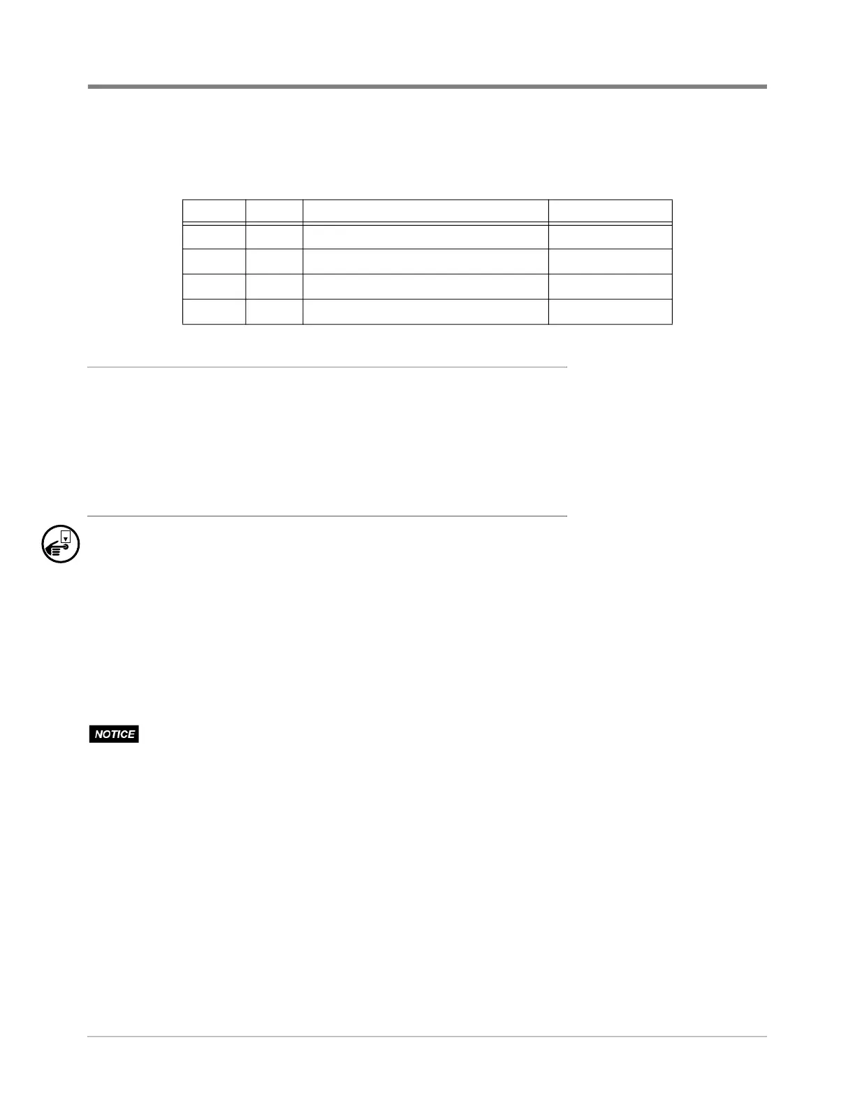
Table 3. Kit - VPS Drying Tube (P/N 330020-717)
Item Qty. Description P/N
1 1 Drying tube - non-indicating desiccant 514100-424
2 36” Tubing - Tygon fuel and lube 514110-425
3 4 Tie wrap 510901-337
4 2 Self-adhesive mount - tie wrap 576008-437