12 Installation Manual
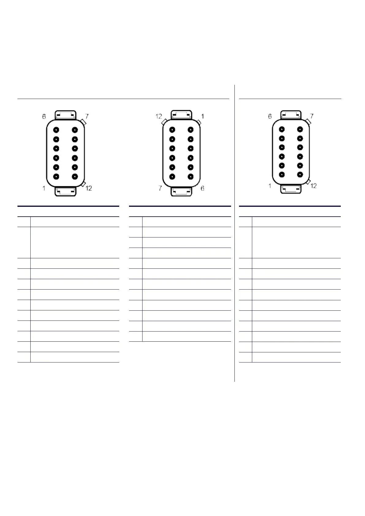
SECONDARY CONNECTOR
1 Senor 1 - analogue input
2 Senor 2 - analogue input
3 Senor 3 - analogue input
4 Senor 4 - analogue input
5 Senor 5 - analogue input
6 Senor 6 - analogue input
7 Senor 7 - analogue input
8 Digital input / flow senor 1
9 Digital input / flow senor 2
10 Tachometer inpu
11 RS232 Receiver
12
RS232 Transmit
PRIMARY CONNECTOR
1 Power - Ground
2
Power (10-32V DC) Supply
should be protected by
500mA - rated circuit breaker
/ fuse
3 RS232 Transmit
4 Ground
5 Ground
6 RS232 Recieve
7 CAN Data L
8 CAN Data H
9 Not Used
10 Not Used
11 Not Used
12
Not Used
C3i / C3il C3 / C3l
PRIMARY CONNECTOR
1 Ground
2
Power (10-32V DC) Supply
should be protected by
500mA - rated circuit breaker
/ fuse
3 Relay / solenoid Output 1
4 Relay / solenoid Output 2
5 Isolated CAN Supply (-)
6 Isolated CAN Supply (+)
7 Isolated CAN Data H
8 Isolated CAN Data L
9 Relay / solenoid Output 3
10 Relay / solenoid Output 4
11 Primary CAN Data H
12
Primary CAN Data L
 Loading...